Backlight device and color liquid crystal display apparatus

a liquid crystal display and backlight technology, applied in semiconductor devices, optics, instruments, etc., can solve the problems of poor color purity of the color filter described above, ccfl, mercury in the phosphorescent tube, and may not cope with the current television broadcasting sufficiently, so as to achieve the effect of suppressing the color mixing of green color

Active Publication Date: 2010-02-16
SATURN LICENSING LLC
View PDF6 Cites 67 Cited by
  • Summary
  • Abstract
  • Description
  • Claims
  • Application Information

AI Technical Summary

Benefits of technology

[0015]The backlight device according to the present invention generates white light and illuminates the transmissive color liquid crystal display panel from its backside with this white light. The color filter includes a tristimulus filter for wavelength-selecting and transmitting green light, red light and blue light. By so doing, the red light, green light and blue light, emitted by the green red light emitting diode, green light emitting diode and by the blue light emitting diode, as the light source, may be improved in color purity to provide for a broad color gamut of the white light generated on color mixing. It is possible to achieve a color reproducing range which will give the NTSC (National Television System Committee) which is not lower than 100%.
[0018]This backlight device generates white light and illuminates a transmissive color liquid crystal display panel with this white light from its back side. The display panel includes a color filter formed by a tristimulus filter for wavelength-selecting and transmitting red light, green light and blue light. By so doing, it is possible to improve color purity of red light, green light and blue light emitted by the red light emitting diode, green light emitting diode and the blue light emitting diode, respectively, in order to provide for a broad color gamut of the white light obtained on color mixing. Hence, it is possible to achieve a color reproducing range corresponding to not less than 100% of the NTSC ratio. It is noted that, in optimizing the color gamut of the color liquid crystal display apparatus, having the light emitting diodes as the light source, the range of chromaticity point of each color light, emitted by the red light emitting diode, green light emitting diode or the blue light emitting diode, is determined. Consequently, the optimum color gamut may be reproduced more correctly than in case only the wavelength of each light emitting diode is determined for optimizing the color gamut.
[0021]Moreover, the half-value width of the light emission spectrum of the green light emitting diode is 30 to 40 nm, which is narrower than in a conventional apparatus, and hence it is possible to suppress color mixing of green color with other colors, especially blue color. In this manner, the color reproducing range of the color liquid crystal display apparatus may be made broader in the green color region than in the conventional system with the broader half-value width.

Problems solved by technology

Hence, the color reproduced by the combination of the backlight device, having such CCFL, emitting the light of three wavelength ranges, as light source, and the color liquid crystal display panel, having the color filter, described above, is rather poor in color purity.
That is, the first-stated color reproducing range may not be said to cope sufficiently with the current television broadcasting.
On the other hand, there is a fear that the CCFL, containing mercury in the phosphorescent tube, may have an ill effect on the environment.
However, there is a problem that the color reproducing range of the color liquid crystal display apparatus, employing light emitting diodes as light source, is not as yet broad enough to satisfy the color reproducing range provided by the NTSC system.

Method used


Image

  • Backlight device and color liquid crystal display apparatus
  • Backlight device and color liquid crystal display apparatus
  • Backlight device and color liquid crystal display apparatus

Examples


Embodiment Construction

[0071]Referring to the drawings, preferred embodiments of the present invention will be described in detail. It should be noted that the present invention is not to be limited to the embodiments now explained and may optionally be modified without departing from the scope of the invention.

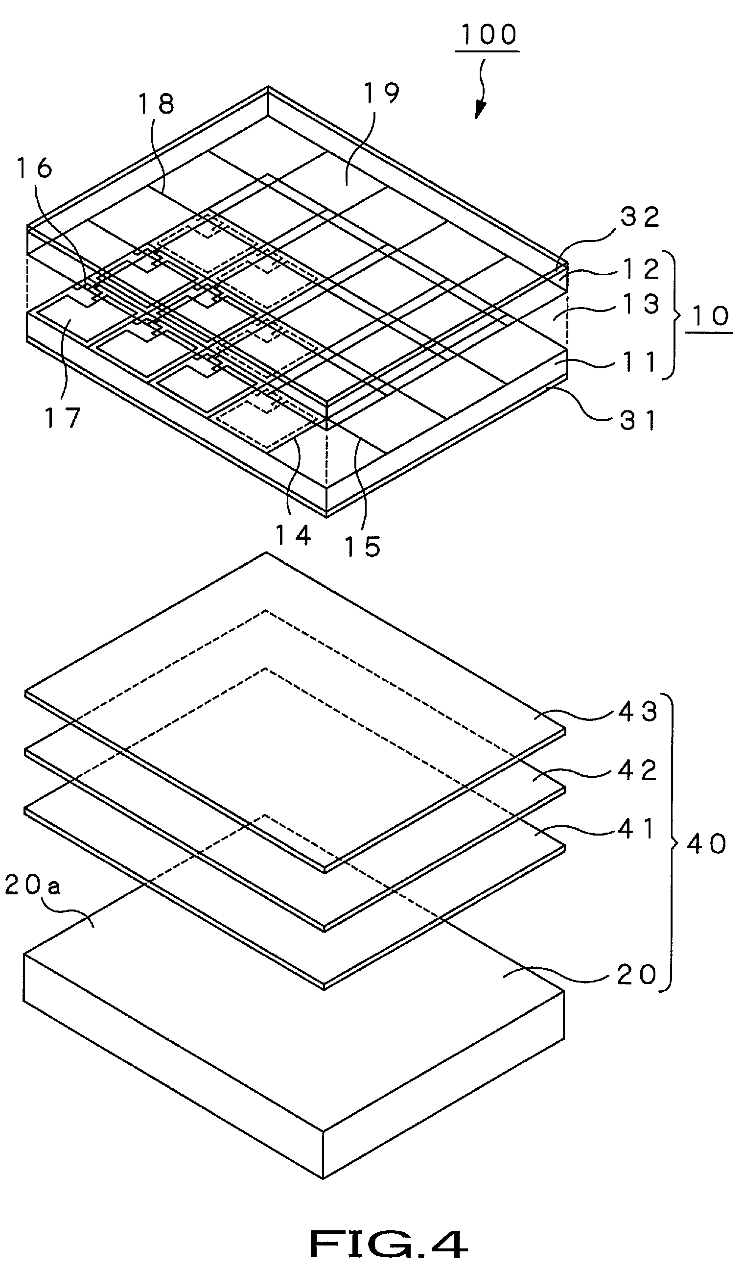
[0072]The present invention is applied to, for example, a color liquid crystal display apparatus 100 configured as shown in FIG. 4.

[0073]In this figure, the transmissive color liquid crystal display apparatus 100 is made up of a transmissive color liquid crystal display panel 10, and a backlight unit 40, provided on the backside of this color liquid crystal display panel 10. This transmissive color liquid crystal display apparatus 100 may be provided with receiving units, such as an analog tuner or a digital tuner, not shown, for receiving the ground wave or the satellite wave, a picture signal processing unit or an audio signal processing unit, not shown, for processing picture signals or audio si...


PUM

PropertyMeasurementUnit
widthaaaaaaaaaa
widthaaaaaaaaaa
half-value width hwraaaaaaaaaa

Abstract

Disclosed is a backlight device used for a color liquid crystal display (LCD) apparatus. The red light, green light and blue light, generated by a light source, made up by a red light emitting diode (21R), a green light emitting diode (21G) and a blue light emitting diode (21B), respectively, are mixed together to generate white light. The red light has a half-value width hwr such that 15 nm≦hwr≦30 nm, and the green light has a half-value width hwg such that 25 nm≦hwg≦50 nm. The blue light has a half-value width hwb such that 15 nm≦hwb≦30 nm. The white light illuminates a transmissive color liquid crystal display panel (10) from its back side. The transmissive color liquid crystal display panel includes a color filter (19) made up by a tristimulus filter for wavelength-selecting and transmitting red light, green light and blue light.

Description

TECHNICAL FIELD[0001]This invention relates to a color liquid crystal display (LCD) apparatus and, more particularly, to a color liquid crystal display apparatus with which the color gamut is made broader to assure more faithful color reproducing performance.[0002]The present application claims priority rights on the basis of the Japanese Patent Applications 2004-238787, 2004-238789 and 2005-075500, filed in Japan on Aug. 18, 2004, on Aug. 18, 2004 and on Mar. 16, 2005, respectively. The contents of these Patent Applications are to be incorporated by reference in the present application.BACKGROUND ART[0003]A TV receiver of an extremely thin thickness, such as one employing a liquid crystal display (LCD) or a plasma display panel (PDP), has been developed and put to practical use to take the place of a TV receiver employing a cathode ray tube (CRT) which has long been used since the start of TV broadcasting. In particular, a color liquid crystal display apparatus employing a color li...

Claims


Application Information

Patent Timeline
Patent Type & Authority Patents(United States)
IPC IPC(8): G02F1/1335H01L33/48
CPCG02F1/133603G02F2001/133624G02F1/133624G02F1/1335
Inventor HAGA, SHUICHIKAKINUMA, KOICHIRONAKATSUE, TAKEHIROMATSUMOTO, TATSUHIKOTAGAWA, YASUHIROOTA, YUTAKAOKU, TAKASHIARAI, TAKEO
Owner SATURN LICENSING LLC
Why Eureka
Try Eureka