Rotating power connector for electric welding torch unicables

a technology of rotating power connector and welding torch, which is applied in the direction of flexible/turnable line connector, coupling contact member, coupling device connection, etc., can solve the problems of mechanical wear and eventual failure of the electrical connection of the welding torch, and achieve the effect of reducing mechanical wear and eliminating any torque in the unicabl

Active Publication Date: 2010-02-23
ILLINOIS TOOL WORKS INC
View PDF10 Cites 33 Cited by
  • Summary
  • Abstract
  • Description
  • Claims
  • Application Information

AI Technical Summary

Benefits of technology

[0006]The present invention provides a rotating power connection that may be affixed either at the front of a torch behind the gooseneck position or at the rear of the torch before the power connection to a wire feeder. The present invention advantageously allows for rotation of the welding torch relative to the unicable. The rotating power connection is connected to a unicable of the torch. When the torch is mounted on a robot arm, the rotating power connection allows the unicable to rotate with the axis of rotation of the robot, thereby eliminating any torque in the unicable and reducing mechanical wear of the unicable.

Problems solved by technology

The conventional fixed connection limits the torsional movement of the copper bundles within the unicables and creates stress, leading to eventual failure of the electrical connection of the welding torch.
In newer robotic designs, this becomes problematic as the cable can be subjected to severe mechanical wear such that the fixed cable connections fail.
In the case of a coaxial mounted welding torch, any rotation of the robot axis that is coaxial with the cable puts rotational torque on the cable, thereby creating mechanical wear.

Method used


Image

  • Rotating power connector for electric welding torch unicables
  • Rotating power connector for electric welding torch unicables
  • Rotating power connector for electric welding torch unicables

Examples


Embodiment Construction

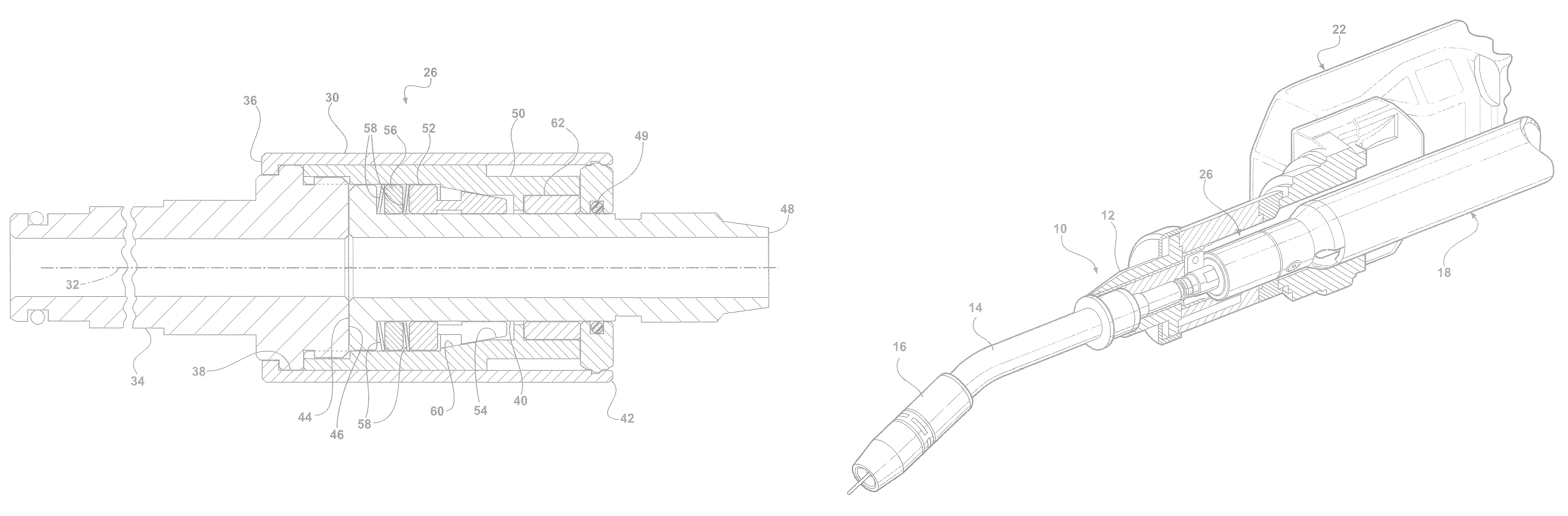
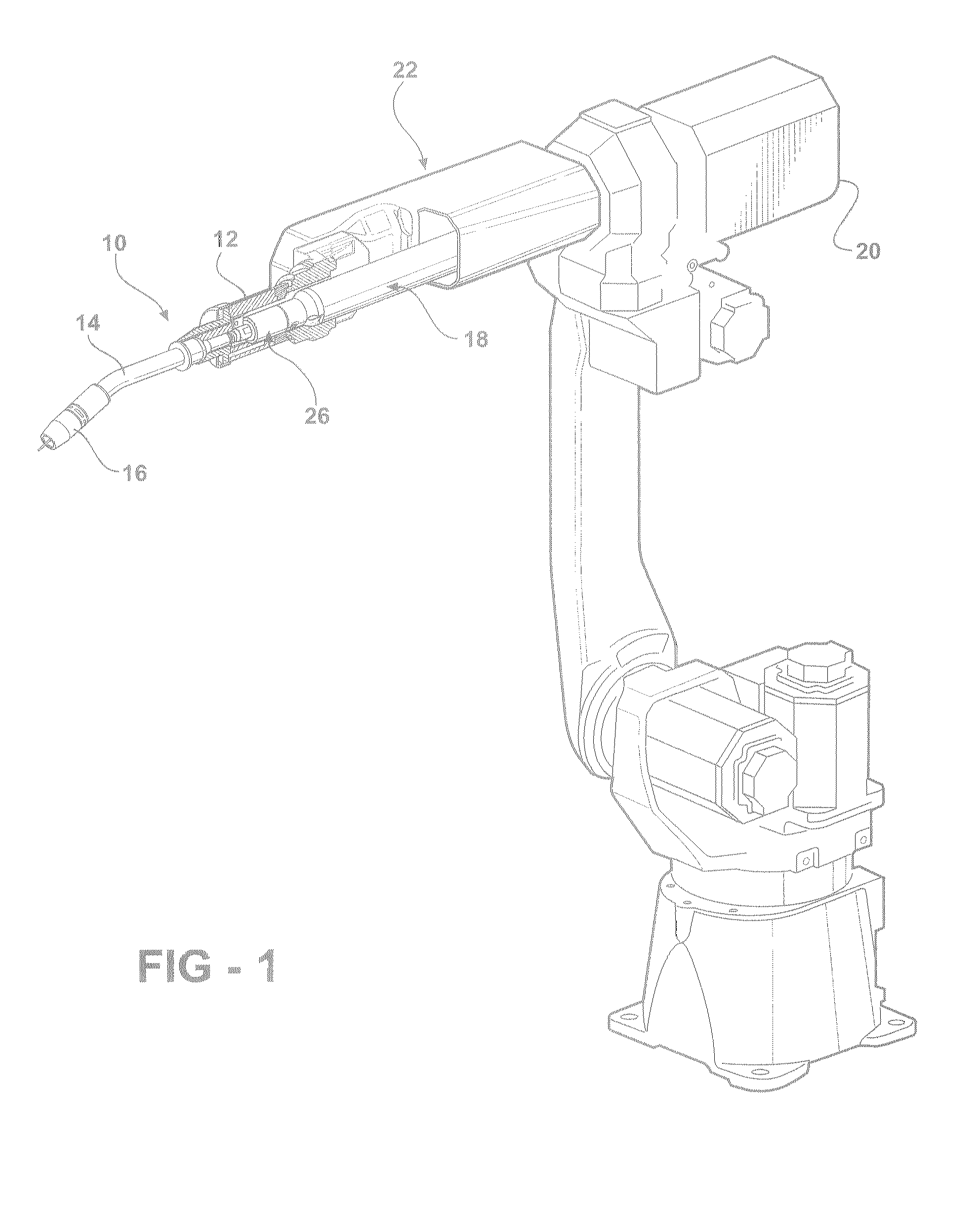
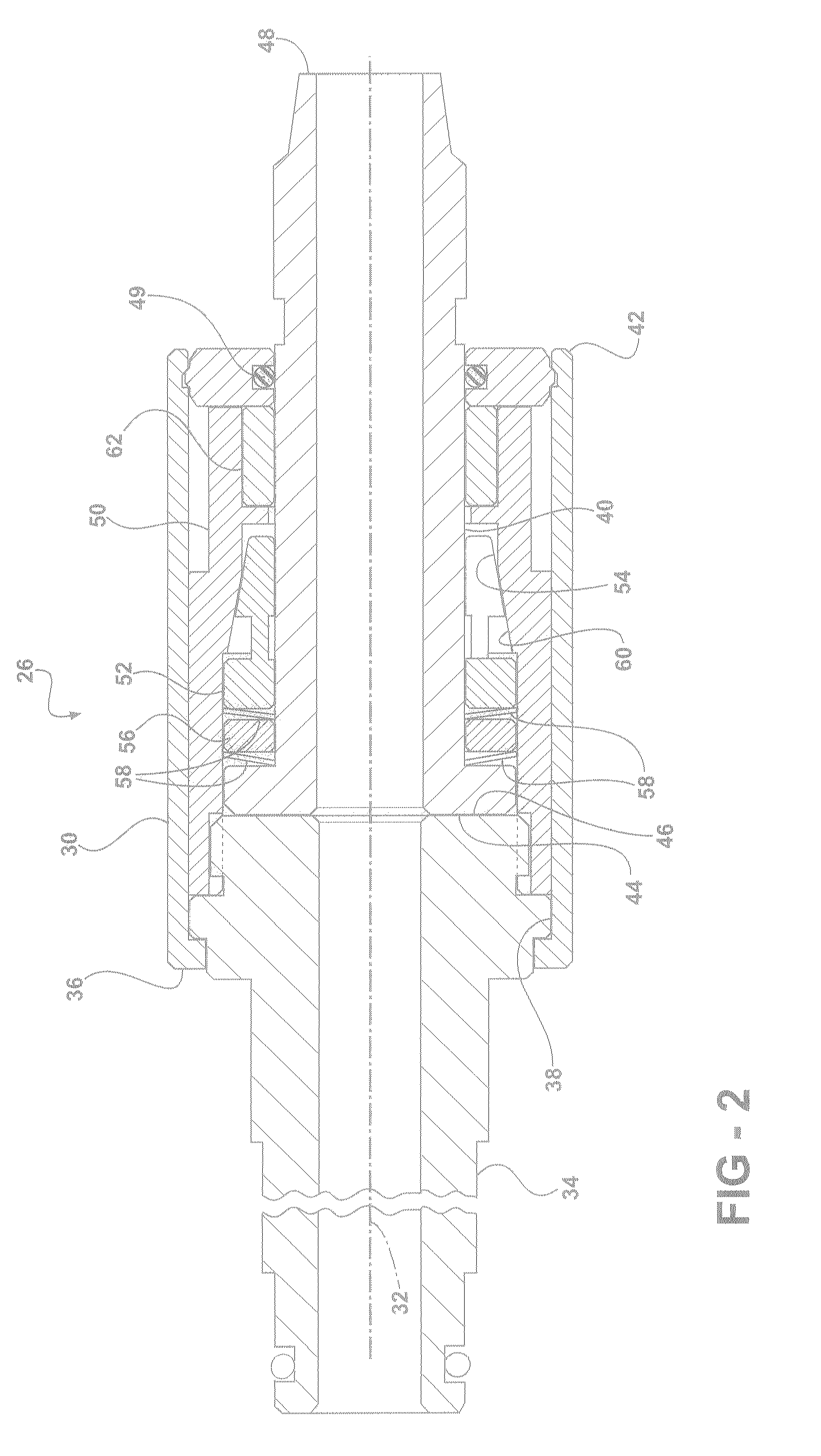
[0021]Referring now to the drawings in detail, numeral 10 generally indicates an electric welding torch such as a gas metal arc welding (GMAW) torch, a metal inert gas (MIG) torch, or similar welding torch. The welding torch 10 includes a main housing 12, a gooseneck 14, and a contact tip assembly 16. An electric power cable such as a unicable assembly 18 is connected to a rearward end of the main housing 12 to supply gas, electrical current, and a consumable electrode (e.g., a metal welding wire) to the torch 10. The unicable assembly 18 generally includes a core tube, copper cabling, and shielded lead wires. The unicable 18 may be connected to a wire feeder 20 opposite the main housing 12 of the welding torch 10. The gooseneck 14 is operatively connected to a forward end of the main housing 12 and allows for the communication of the consumable electrode, the shielding gas, and the welding current to the contact tip assembly 16 mounted on the gooseneck. The welding torch 10 is coax...


PUM


Abstract

A rotating power connector for an electric welding torch unicable includes a generally cylindrical outer housing having a longitudinal axis. A connector pin is fixedly, axially disposed within the outer housing and extends from one end thereof. A rotating stud is rotatably, axially disposed within the outer housing and extends from another end thereof. The connector pin and the rotating stud have ends in contact within the outer housing. A secondary electrical contact ring also is disposed within the outer housing. The secondary electrical contact ring includes at least one contact portion contacting the rotating stud. At least one biasing member is disposed between the rotating stud and the contact ring. The biasing member urges the rotating stud into engagement with the connector pin and urges the contact ring into engagement with the rotating stud.

Description

CROSS REFERENCE TO RELATED APPLICATION[0001]This application claims the priority of U.S. Provisional Application No. 60 / 899,301 filed Feb. 2, 2007.TECHNICAL FIELD[0002]This invention relates to electric welding and specifically to a rotating power connection for connecting an electrical supply power cable to an electric welding torch.BACKGROUND OF THE INVENTION[0003]In an electric welding process, it is known to use a power cable for conducting current and sometimes shielding gas to a welding torch. The power cable is often referred to as a unicable, which generally includes a core tube, copper cabling and shielded lead wires. Typically, such a cable is connected to each end of a MIG torch by way of either a crimped style fitting or a threaded compression fitting. One end of the cable is fastened to a wire feeder by way of a mating pin, and the other end is fastened to a gooseneck or conductor tube of the welding torch. These connections are fixed and unmoving.[0004]The conventional...

Claims


Application Information

Patent Timeline
Patent Type & Authority Patents(United States)
IPC IPC(8): H01R39/00
CPCH01R35/04H01R9/11
Inventor JAEGER, THOMAS
Owner ILLINOIS TOOL WORKS INC
Why Eureka
Try Eureka