Differential oscillator device with pulsed power supply, and related driving method

a differential oscillator and power supply technology, applied in pulse automatic control, oscillation generators, resonance circuit tuning, etc., can solve the problems of limited correction of pll circuit, particularly complex circuit, and unsatisfactory synthesised sources, so as to improve the phase noise characteristics of the integrated oscillator and the effect of easy addition to the integrated circui

Inactive Publication Date: 2010-02-23
UNIV DEGLI STUDI DI ROMA LA SAPIENZA
View PDF11 Cites 7 Cited by
  • Summary
  • Abstract
  • Description
  • Claims
  • Application Information

AI Technical Summary

Benefits of technology

[0026]It is still an object of the present invention to use even complex circuits, which may be easily added to an integrated circuit without appreciable burden of dissipated power, for improving the phase noise characteristics of the integrated oscillator.
[0031]Still according to the invention, said generator electronic means may be capable to supply said at least one power supply pulsed signal to said resonant electronic means in instants at which the effects of the orbital deviations due to the projections of a vector representative of said at least one power supply pulsed signal on the Floquet eigenvectors of the state variables of the circuit as a whole are minimised to the aim of the phase noise.

Problems solved by technology

In particular, the circuit is particularly complex and comprises a frequency and phase detector, driven by a oscillating reference signal, that generates through a proper filter a control voltage of the VCO, from which it draws a feedback signal, through a frequency divider.
In spite of the control and correction mechanism with which a Vco is provided, the synthesised source is not ideal: random frequency variations around the nominal value are present.
In this interval the correction of the PLL circuit is limited, sometimes greatly, by the band of the feedback loop, that in turn is limited for stability problems.
A first source of alteration of the oscillator evolution is due to the noise present in the electronic circuits, in particular in the parasitic resistances of the reactive components of the resonant circuit representing the oscillator time reference, partly in the circuits which must periodically supply the resonant circuit with the energy lost during the oscillation just because the parasitic resistances.
However, no one of the oscillators available nowadays, among the previously mentioned ones, has a low phase noise, though some of them have rather complex circuit architectures.

Method used


Image

  • Differential oscillator device with pulsed power supply, and related driving method
  • Differential oscillator device with pulsed power supply, and related driving method
  • Differential oscillator device with pulsed power supply, and related driving method

Examples


first embodiment

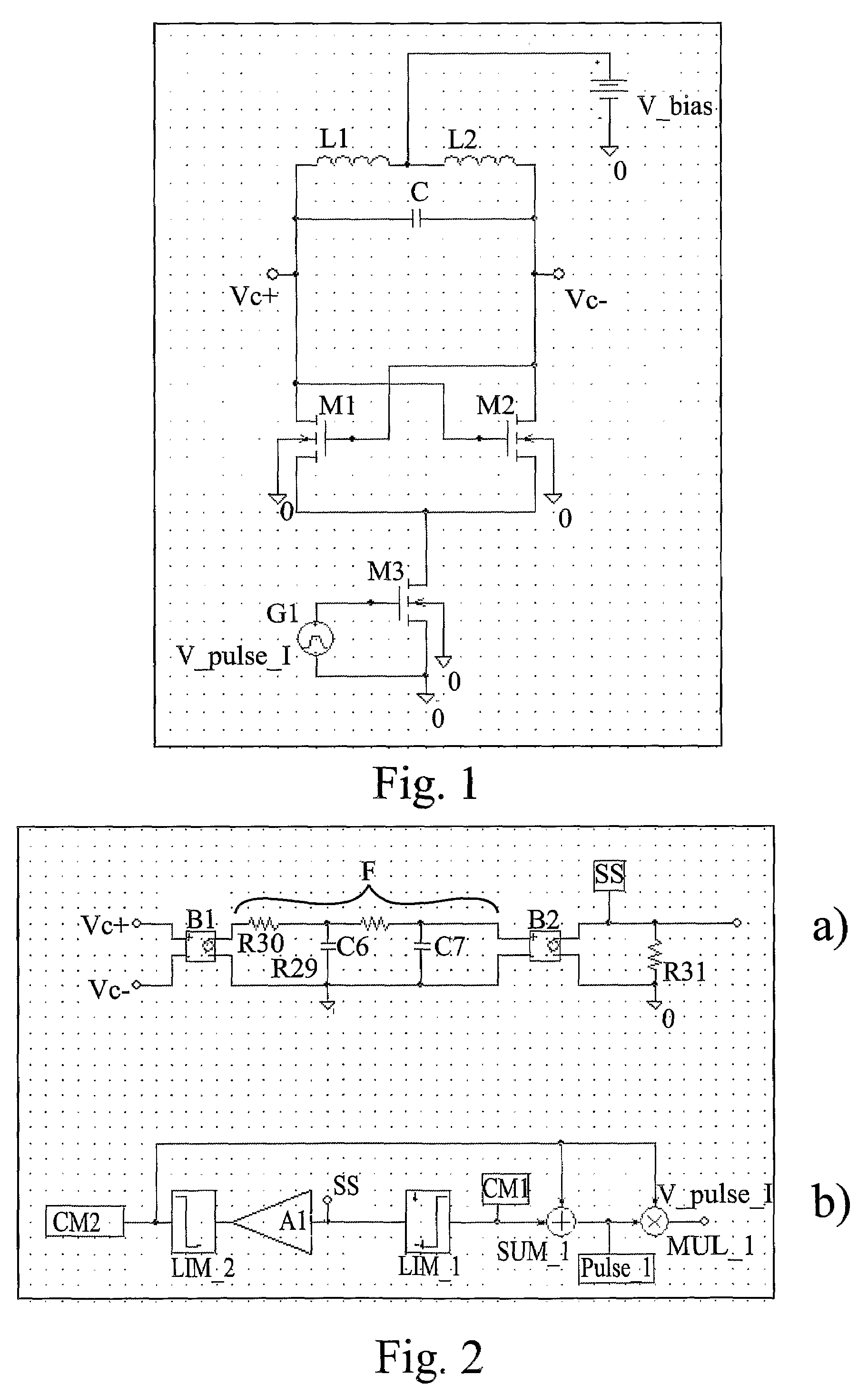
[0076]With reference to FIG. 1, it may be observed a first configuration of the differential oscillator, substantially based on the use of the classical differential oscillator, that is part of the device according to the invention. In particular, the oscillator of FIG. 1 is made with MOS transistors, wherein a resonant circuit comprises two inductors L1 and L2 (preferably of equal inductance), series-connected and between which the power supply voltage V_bias is connected, which are connected in parallel to a capacitor C, across which the oscillating signal VOUT=VC+−VC− generated by the device of FIG. 1 is drawn.

[0077]The resonant circuit is connected, according to a conventional differential configuration, to two n-type MOS transistors M1 and M2, operating as switches, to the source terminals of which the drain terminal of a n-type transistor MOS M3 is connected, that operates as current generator, the source terminal of which is connected (as well as the substrates of the three t...

second embodiment

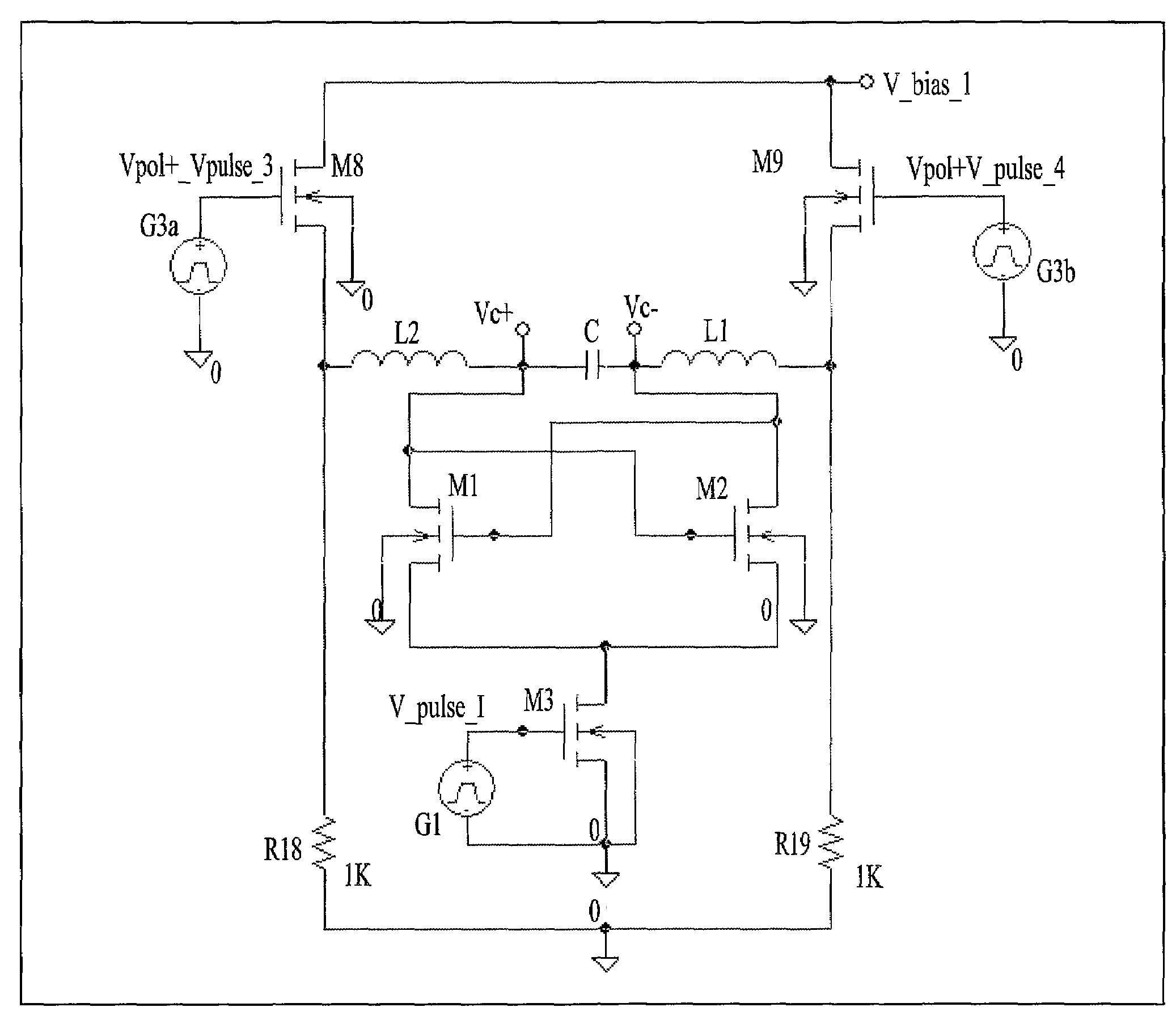
[0092]With reference to FIG. 6, a possible double power supply implementation of the configuration of FIG. 5 may be observed, that is part of the device according to the invention. In particular, the oscillator of FIG. 6 is made with MOS transistors: each one of the two ends of the series resonant circuit is connected to the drain terminals of a respective pair of n-type and p-type MOS transistors (respectively, the pair M4 and M6, and the pair M5 and M7), also having gate terminal in common. The source terminals of the two p-type MOS transistors M6 and M7 are connected (as well as the respective substrates) to a first power supply voltage V_bias_1 (that is preferably positive), while the source terminals of the two n-type MOS transistors M4 and M5 are connected (as well as the respective substrates) to a second power supply voltage V_bias_2 (that is preferably negative, still mote preferably equal to the circuit ground, i.e. to zero, for simplifying the structure). Two pulsed volta...


PUM


Abstract

The present invention concerns a differential oscillator device, comprising resonant electronic means, capable to provide on at least two terminals at least one oscillating signal VOUT, which comprises a generator electronic means capable to supply at least one power supply pulsed signal to said resonant electronic means in phase relation with said at least one oscillating signal VOUT. The present invention further concerns a process of supplying pulsed power to such a differential oscillator device.

Description

CROSS-REFERENCE TO RELATED APPLICATIONS[0001]This application is a 35 U.S.C. §371 of International Application No. PCT / IT2005 / 000756 filed Dec. 22, 2005, which claims priority from Italian patent application RM2004A000648, filed Dec. 30, 2004, the entire contents of which including amendments made in the International Application, are incorporated herein by reference.FIELD OF THE INVENTION[0002]The present invention relates to a differential oscillator device with pulsed power supply that has a substantially neglectable phase noise and a high power supply noise rejection, being simple, reliable, efficient, precise, and capable to generate oscillating signals even at high frequencies, also entailing a reduced power consumption. The device according to the invention is further usable in very many applications wherein the generation of an oscillating signal is required.[0003]The present invention further relates to the related process for providing the pulsed power supply to the differ...

Claims


Application Information

Patent Timeline
Patent Type & Authority Patents(United States)
IPC IPC(8): H03B5/00
CPCH03B5/04H03B5/1228H03B5/1215
Inventor PALMA, FABRIZIO
Owner UNIV DEGLI STUDI DI ROMA LA SAPIENZA
Why Eureka
Try Eureka