Air conditioning apparatus

a technology of air conditioning apparatus and heating medium, which is applied in the direction of refrigeration components, refrigeration machines, process and machine control, etc., can solve the problem of not having the necessary air conditioning function, and achieve the effect of improving heat transfer efficiency between heating mediums and effectively storing hea

Inactive Publication Date: 2010-03-02
TOYOTA JIDOSHA KK
View PDF21 Cites 41 Cited by
  • Summary
  • Abstract
  • Description
  • Claims
  • Application Information

AI Technical Summary

Benefits of technology

[0006]More specifically, an object of the invention is to provide an air conditioning system capable of improving fuel consumption by mitigating an impact on an engine load due to an air conditioning demand, in case it is mounted on a vehicle.
[0008]The first heating medium is heated or cooled by using a power unit such as an engine, motor and the like, and does not exchange heat with air. Therefore, the first heating medium can be heated or cooled independently from the air conditioning demand. This mitigates direct impact on the load of the power unit due to the air conditioning demand.
[0011]In the first heat exchanger, the flow passage which the first heating medium flows through, and the flow passage which the second heating medium flows through, are formed adjacent to and in parallel with each other, and the flowing directions of each heating medium can be made opposite to each other. With this construction, heat transfer efficiency between the heating mediums can be improved.
[0012]The third heat exchanger can be constructed of a heat storing device having a heat storage material therein which is heated or cooled by the first heating medium. In this case, heat capacity of the third heat exchanger is larger than that of the first heat exchanger. Therefore, the second heating medium is flown to the first heat exchanger to execute cooling in response to the rapid cooling demand, and the second heating medium is flown to the third heat exchanger to execute cooling in response to the normal cooling demand, in order to use the stored heat effectively.
[0019]For heating or cooling the first heating medium of the invention, it is possible to use a mechanism including a compressor for compressing the first heating medium, a heat radiator for radiating heat from the compressed and high-temperatured first heating medium, and a expander for adiabatically expanding the first heating medium. The compressor, the heat radiator and the expander can be connected in series with the first heat exchanger and the first heat storing device. The second heat storing device is preferably connected right behind a discharging port of the compressor. Thus, the heat of the first heating medium is more recovered by the second heat storing device. As a result, a load on the heat radiator is reduced so that the heat radiator can be downsized. In addition, in case of compulsory cooling, energy consumed by a blowing fan can be saved.

Problems solved by technology

This makes it probable that necessary air conditioning function cannot be obtained.

Method used


Image

  • Air conditioning apparatus
  • Air conditioning apparatus
  • Air conditioning apparatus

Examples


Embodiment Construction

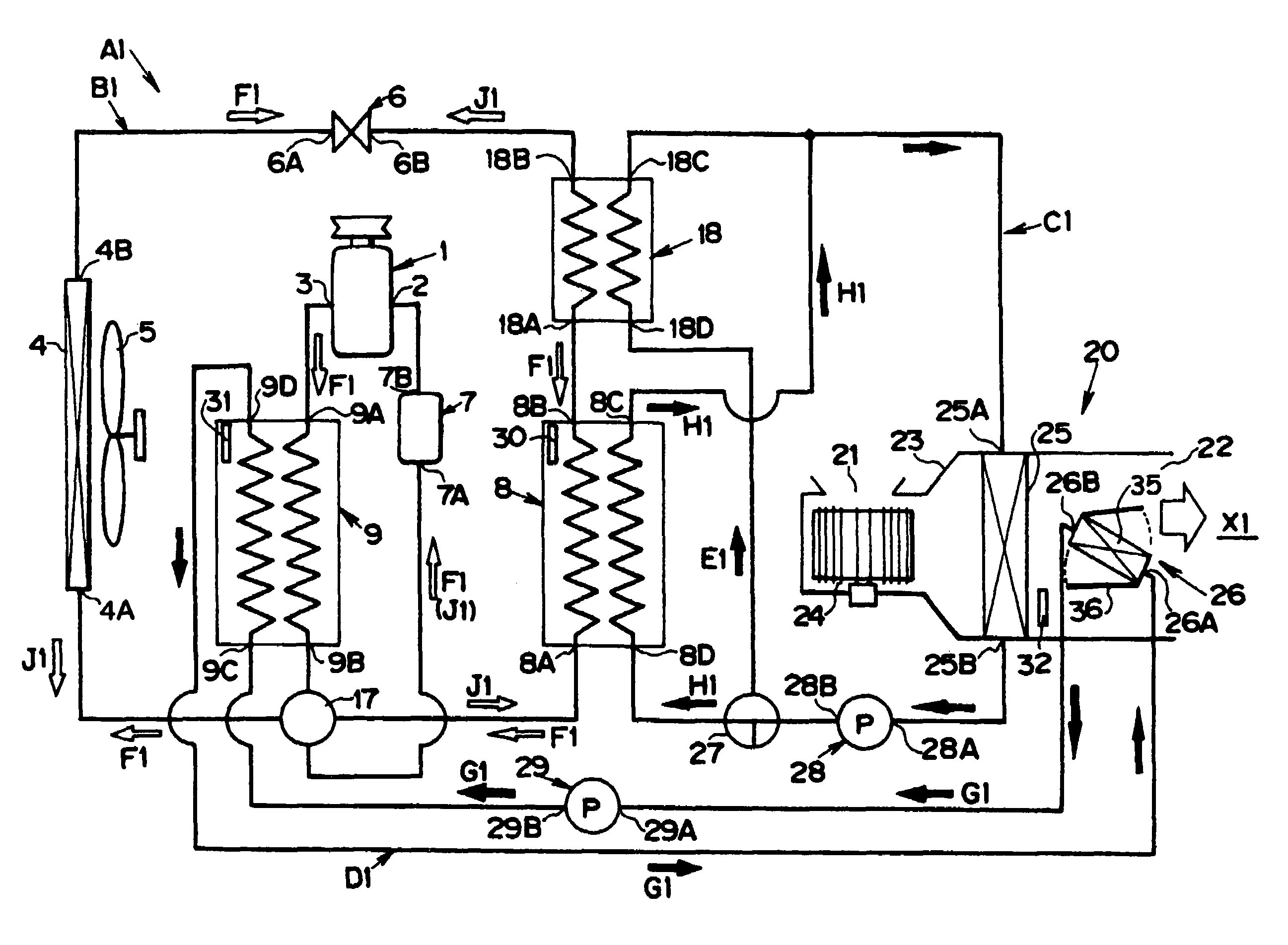
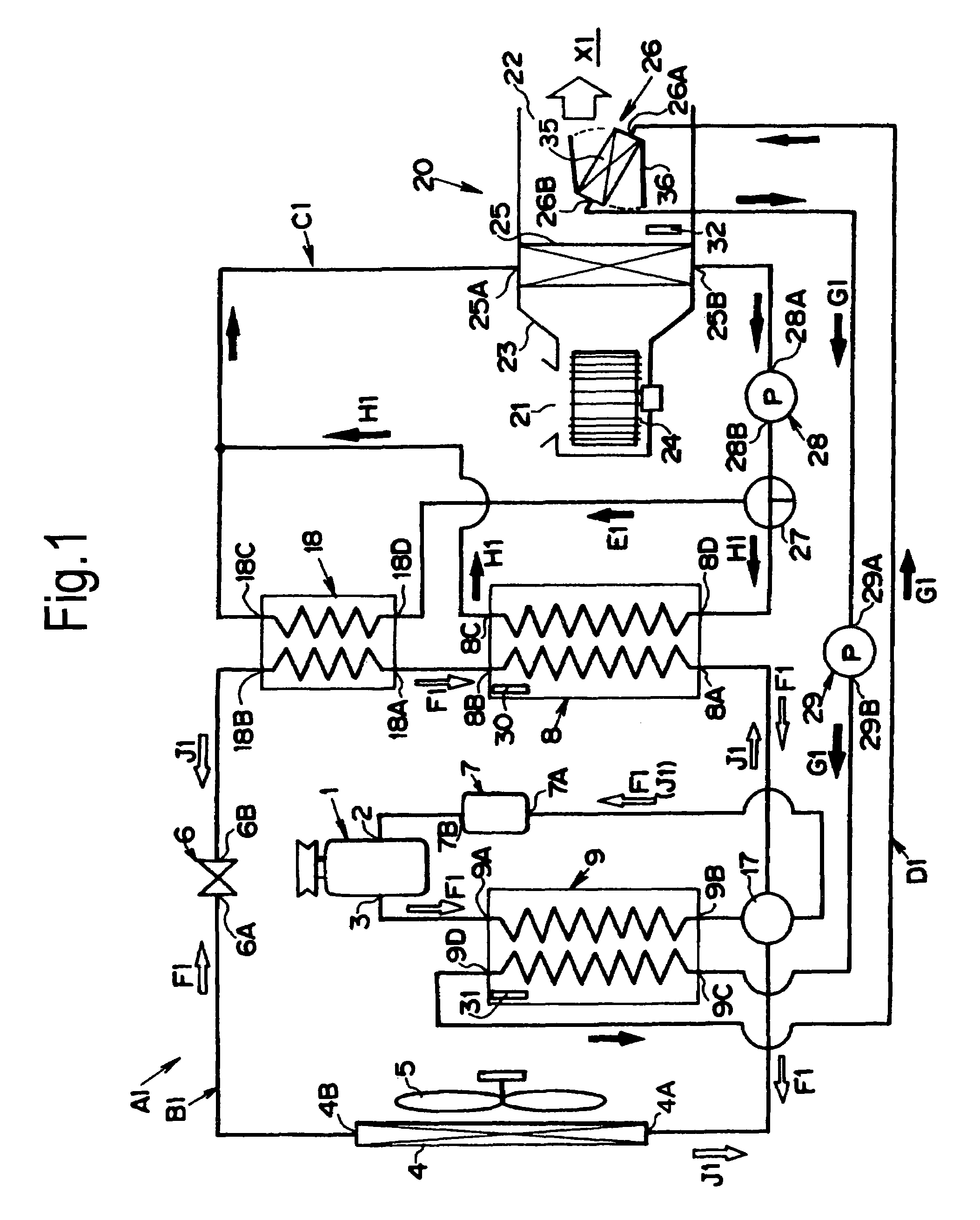
[0041]This invention will be described with reference to the accompanying drawings. FIG. 1 is a conceptional diagram showing a construction of an air conditioning system A1 for a vehicle. The air conditioning system A1 has a first circuit B1, a second circuit C1 and a third circuit D1. Each circulation circuit is, specifically, a flow passage for a fluid having a piping. A refrigerant (e.g., chlorofluorocarbon or refrigerant gas containing no chlorine) flows through the first circuit B1, whereas a brine (e.g., water or saltwater) flows through the second circuit C1 and the third circuit D1.

[0042]A construction of the first circuit B1 will be described first. A compressor 1 is arranged in the first circuit B1, which has a suction port 2 and a discharging port 3. The compressor 1 is driven by an (later-described) engine or an (later-described) electric motor. On the other hand, an outdoor heat exchanger 4 is arranged in the first circuit B1. This outdoor heat exchanger 4 is exemplifie...


PUM


Abstract

An air conditioning system for cooling or heating an air, and for feeding the heated or cooled air to predetermined portions is characterized by comprising: a first circulating circuit for circulating a first heating medium; a second circulating circuit for circulating a second heating medium; a control unit for controlling the heat for executing heat exchange between the first heating medium and the second heating medium to flow through either the heat exchanger or the first heat storing device. Moreover, an air temperature is controlled by heat of the second heating medium.

Description

TECHNICAL FIELD[0001]This invention relates to an air conditioning system for executing a heat exchange among a plurality of heating mediums, thereby controlling air temperature on the basis of the exchanged heat.BACKGROUND ART[0002]An air conditioning system for a vehicle is generally constructed to regulate a room temperature by a refrigeration cycle for circulating a refrigerant. The air conditioning system of this kind is disclosed in Japanese Patent Laid-open No. 2000-142078. According to an air conditioning system for a vehicle disclosed in the Laid-open, a compressor, a condenser, a receiver, an expansion valve, an evaporator and so on are arranged in a circulating circuit of the refrigerant. In a casing of the air conditioning system, a blower fan and an evaporator are arranged. Moreover, an air inlet and an air outlet are formed on the casing.[0003]Here will be explained an operation example according to the aforementioned air conditioning system. First of all, when the blo...

Claims


Application Information

Patent Timeline
Patent Type & Authority Patents(United States)
IPC IPC(8): B60H1/00F25B29/00B60H1/22B60H1/32F25B13/00F25B25/00F25B27/00F25B40/04F25B47/02F28D7/00F28D9/00F28D20/00
CPCB60H1/00492B60H1/00892B60H1/3204F25B13/00F25B25/005F25B27/00F25B40/04F25B47/025F28D7/0016F28D9/005F28D20/00B60H2001/00928B60H2001/00935F25B2313/02341F25B2313/02344F25B2327/001F25B2400/24Y02E60/142B60H1/32281Y02E60/14B60H1/00885B60H1/3228
Inventor TSUBONE, KENJIAIKAWA, YASUKAZUHIJIKATA, YASUTANE
Owner TOYOTA JIDOSHA KK
Why Eureka
Try Eureka