Laser ablative synthesis of carbon nanotubes

a carbon nanotube and laser ablative technology, applied in the direction of chemistry apparatus and processes, manufacturing tools, electric/magnetic/electromagnetic heating, etc., can solve the problems of limited flowpaths that cannot be readily modified for optimal apparatus operation, and the production apparatus of nanotubes, etc., to achieve easy modification for production efficiency optimization, simplified apparatus, and reduced heat up and cool down time

Inactive Publication Date: 2010-03-02
NASA +1
View PDF0 Cites 5 Cited by
  • Summary
  • Abstract
  • Description
  • Claims
  • Application Information

AI Technical Summary

Benefits of technology

[0008]There therefore remains a significant need for an apparatus and operating method that while capable of producing large volumes of carbon nanotubes provide simplified apparatus, greatly reduced heat up and cool down times and flexible flowpaths that can be readily modified for production efficiency optimization.

Problems solved by technology

Thus, while there exist numerous areas of potential and actual application for SWNTs, what has been, and is currently lacking, is a method for the production of SWNTs of high quality in sufficient quantities as to provide a reliable and adequate source of desirable raw material for the development and implementation of such applications.
While numerous attempts have been made to improve the production rates of these materials, most such attempts have resulted in the design of carbon nanotube production apparatus and operating procedures that were extremely complex due to operating conditions below atmospheric pressure, required extended heat up and cool down times on the order of hours and / or provided limited flowpaths that could not be readily modified for optimal apparatus operation.

Method used


Image

  • Laser ablative synthesis of carbon nanotubes
  • Laser ablative synthesis of carbon nanotubes
  • Laser ablative synthesis of carbon nanotubes

Examples


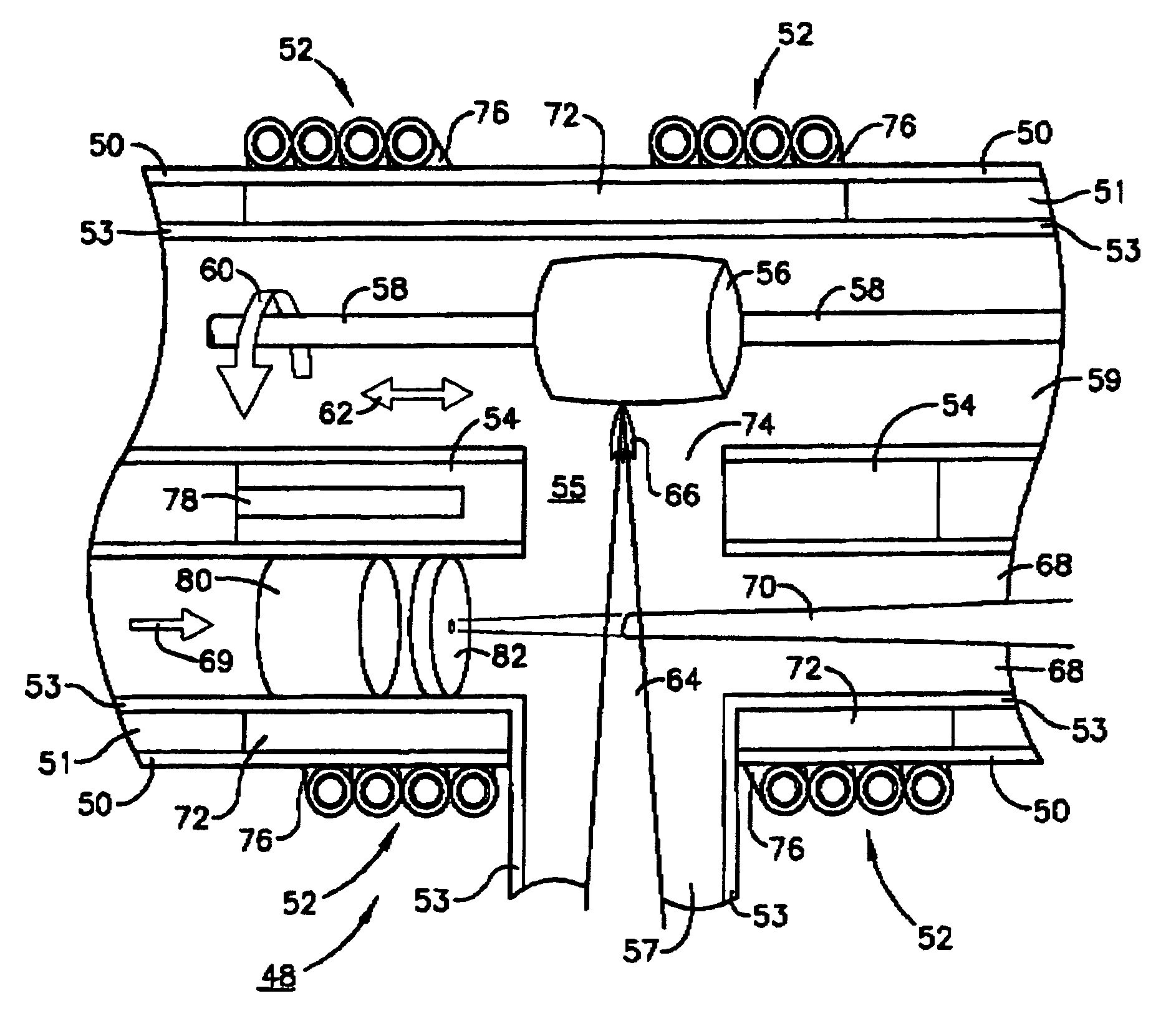
Embodiment Construction

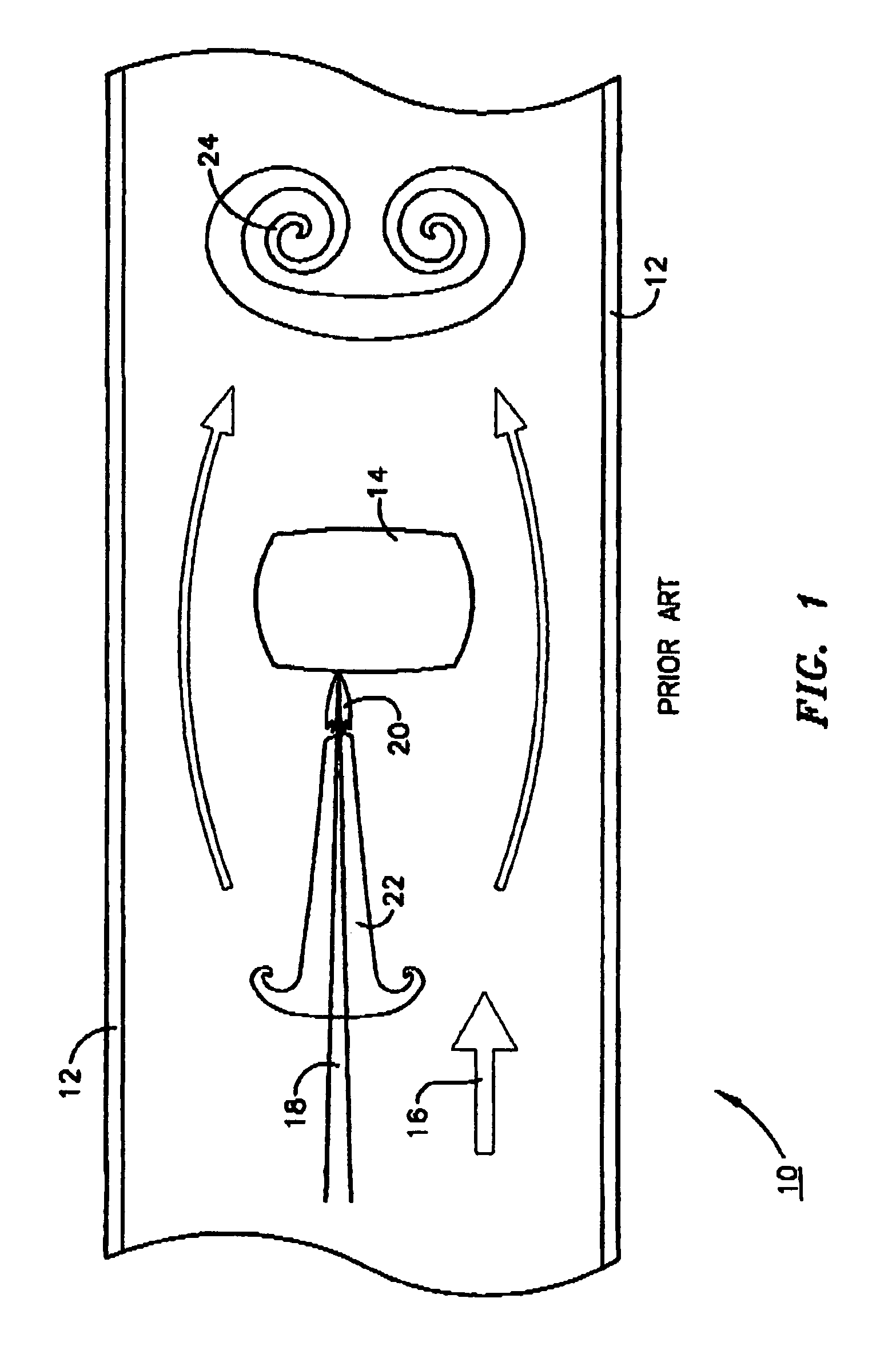
[0014]Referring now to the accompanying drawings, as shown in FIG. 1, the original front-pumped chamber 10 utilized to produce carbon nanotubes included a vacuum chamber 12 maintained at about 500 torr and 1000° C., a graphite / catalyst target 14, an argon flow as depicted by arrow 16 and a laser beam 18 that interacted in well-known fashion to produce a plasma plume 20 that in turn resulted in the formation of a nanotube vortex 22 that, driven by argon flow 16, resulted in movement of vortex 22 toward and onto a target at 24.

[0015]While such an apparatus was capable of producing carbon nanotubes, its production levels were very low and demanded improvement.

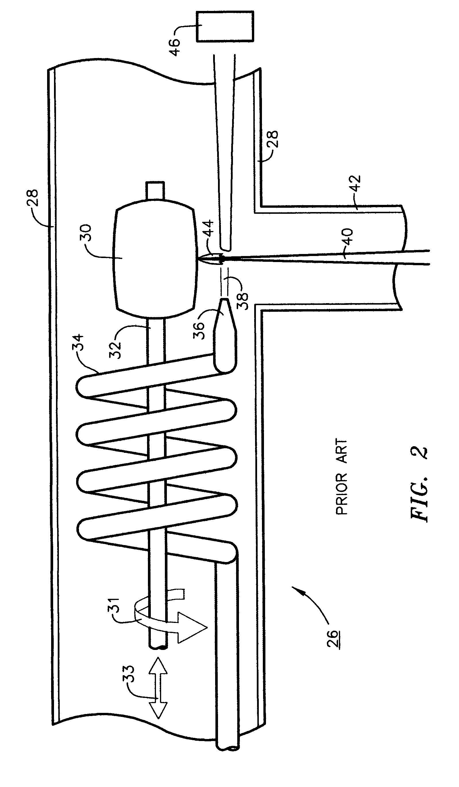
[0016]FIG. 2 depicts one of the first side-pumped synthesis chambers for the production of carbon nanotubes designed to improve the level of production of carbon nanotubes over the levels achievable with the design of FIG. 1.

[0017]As shown in FIG. 2 the prior art side-pumped synthesis chamber 26 comprised a chamber furnace 28 main...


PUM

PropertyMeasurementUnit
temperatureaaaaaaaaaa
lengthaaaaaaaaaa
lengthaaaaaaaaaa

Abstract

An improved method for the production of single walled carbon nanotubes that utilizes an RF-induction heated side-pumped synthesis chamber for the production of such. Such a method, while capable of producing large volumes of carbon nanotubes, concurrently permits the use of a simplified apparatus that allows for greatly reduced heat up and cool down times and flexible flowpaths that can be readily modified for production efficiency optimization. The method of the present invention utilizes a free electron laser operating at high average and peak fluence to illuminate a rotating and translating graphite/catalyst target to obtain high yields of SWNTs without the use of a vacuum chamber.

Description

[0001]The United States of America may have certain rights to this invention under Management and Operating Contract DE-AC05-84ER 40150 from the United States Department of Energy.FIELD OF THE INVENTION[0002]The present invention relates to the synthesis of single-walled carbon nanotubes and more particularly to a novel method for such synthesis using a free electron laser.BACKGROUND OF THE INVENTION[0003]Since the first reports of the production of single-walled carbon nanotubes (hereinafter SWNT) in 1991 by researchers at NEC and IBM, a variety of synthesis routes have been developed to improve both the production rate and the fractional conversion of carbon feedstocks to SWNTs. Among the methods developed for this purpose, all of which are well known and well documented in the art are: Arc Discharge (AD); Pulsed Laser Vaporization (PLV); and Chemical Vapor Deposition (CVD). Much of the work with PLV techniques has been carried out at Rice University as reported by A. Thess et al....

Claims


Application Information

Patent Timeline
Patent Type & Authority Patents(United States)
IPC IPC(8): H05B6/02B23K26/02B23K26/08D01F9/12
CPCB82Y30/00B82Y40/00C01B31/0233C01B2202/02Y10S977/844C01B32/162
Inventor SMITH, MICHAEL W.JORDAN, KEVINPARK, CHEOL
Owner NASA
Why Eureka
Try Eureka