Substrate and substrate module

a substrate and substrate technology, applied in the direction of cross-talk/noise/interference reduction, waveguide devices, waveguide types, etc., can solve the problems of high-frequency characteristic deterioration, high-frequency characteristic deterioration due to displacement of transmission lines in the longitudinal direction and the height direction, and achieve the effect of improving connection strength

Active Publication Date: 2010-03-02
FUJITSU LTD
View PDF1 Cites 3 Cited by
  • Summary
  • Abstract
  • Description
  • Claims
  • Application Information

AI Technical Summary

Benefits of technology

[0016]Accordingly, an object of the present invention is to provide substrates and a substrate module that, regarding the connection of high frequency transmission lines, can keep a high frequency characteristic in a good condition, and maintain the connection strength thereof by easy methods, using the substrates or substrate module for signal transmission.
[0023]According to the construction of an embodiment of the present invention, the base material and the rear surface grounds are partially cut out so that the ground portions of the transmission line arranged on the substrate surface are exposed, and the substrates are connected using the exposed portions. By advantage of this feature, it is possible to keep a frequency characteristic within a band on the level of 40 GHz in a good condition, and secure an enhanced connection strength.

Problems solved by technology

However, under the recent tendency of transmission signals toward high frequencies, when the high frequency transmission lines are connected by an Au wire or an Au ribbon, an impedance-mismatched part in a connection portion can give rise of deterioration of high-frequency characteristic.
Furthermore, with the tendency of transmission signals toward high frequencies, deterioration of high frequency characteristic due to displacements between transmission lines in the longitudinal direction and the height direction also becomes significant.
On the other hand, the way of connecting the substrates via the connector causes a higher cost, a larger size, the need for extra-length processing spaces of coaxial line and the like, and hence, this is unsuitable for size reduction or cost reduction.
When attempting to connect a transmission line on the flexible substrate and another transmission line to secure a band on the level of 40 GHz, it is difficult to keep a high-frequency characteristic in a good condition and maintain a satisfactory connection strength, at the connection portion between the transmission lines.
When attempting to secure a band on the level of 40 GHz and keep a high-frequency characteristic in a good condition, a problem of impedance mismatch can arise.
This problem is attributable to positional displacements and / or position tolerance between substrates, caused by the structure and material of the transmission lines at the connection portion between a substrate and a flexible substrate used for the connection between the substrate and a light receiving / emitting element.
When the surfaces of signal lines in coplanar lines on two substrates are directed in the same direction, the inter-ground distance of each of the two substrates is treated as being equivalent to an inductor, and hence, positional displacements and / or position tolerance between the substrates causes an impedance-mismatch, thereby resulting in degradation of high frequency characteristic.

Method used


Image

  • Substrate and substrate module
  • Substrate and substrate module
  • Substrate and substrate module

Examples


Embodiment Construction

[0039]The present invention is directed to a connection substrate for connecting a substrate on which circuits such as a drive circuit for driving a laser device, and an amplifier for amplifying signals from a photo acceptance device are mounted, to a laser device and / or a photo acceptance device; and directed to a substrate module using the above-described substrate.

[0040]Hereinafter, an embodiment according to the present invention will be described with reference to accompanying drawings. Throughout the drawings, the same or functionally equivalent parts are designated with the same reference numerals.

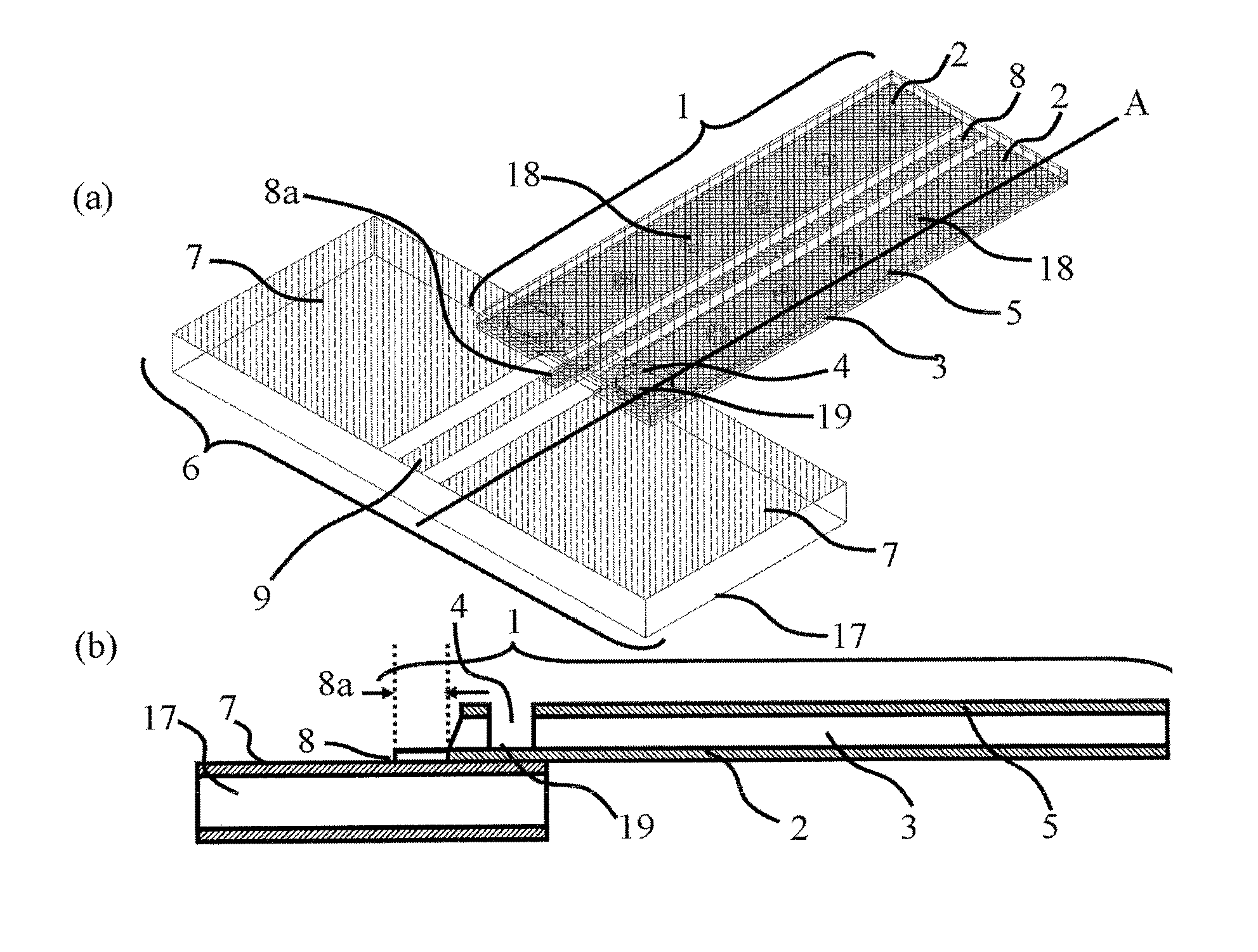
[0041]FIGS. 1A and 1B are each a representation of the embodiment according to present invention. FIG. 1A is a perspective view of a substrate for connection and a substrate on which electric circuitry is mounted. FIG. 1B is a sectional view of these substrates cut taken away along a line A in FIG. 1A.

[0042]The substrate 1 for connecting a light receiving / emitting element between th...


PUM


Abstract

A substrate module includes a first substrate and a second substrate. The first substrate comprises a base material; a transmission line in which a signal line is sandwiched between two ground patterns, on the surface of the base material; a ground pattern on the rear surface of the base material; and an exposed portion in which the ground pattern on the substrate surface is exposed by partially cutting out the base material and the ground pattern on the substrate rear surface. The second substrate comprises a base material and a transmission line in which a signal line is sandwiched between two ground patterns, on the surface of the base material. In connecting a transmission line of the first substrate and that of the second substrate, the ground patterns of the first and second substrates are fused with each other at the exposed portion and fixed.

Description

BACKGROUND OF THE INVENTION[0001]1. Field of the Invention[0002]The present invention relates to a connection of high frequency transmission lines, and more specifically, to the implementation of a connection portion between transmission lines which is capable of keeping a frequency characteristic in a good condition and of which a satisfactory connection strength can be maintained by easy means, through the use of substrates.[0003]2. Description of the Related Art[0004]Hitherto, the high frequency transmission lines has been connected by connecting, using a golden (Au) wire or an Au ribbon, two dielectric substrates on each of which a coplanar transmission line is formed on a signal line between grounds, or the high frequency transmission lines have been packaged and connected by a coaxial line via a connector.[0005]However, under the recent tendency of transmission signals toward high frequencies, when the high frequency transmission lines are connected by an Au wire or an Au ribb...

Claims


Application Information

Patent Timeline
Patent Type & Authority Patents(United States)
IPC IPC(8): H01P5/02
CPCH05K1/0219H05K3/363H05K2201/0394H05K2201/0397H05K2201/0715
Inventor YAGISAWA, TAKATOSHI
Owner FUJITSU LTD
Why Eureka
Try Eureka