
Aerodynamic jetting of aerosolized fluids for fabrication of passive structures

a technology of aerosolized fluids and passive structures, applied in the direction of liquid surface applicators, resistive material coatings, coatings, etc., can solve the problems of large minimum line width, unsuitable process for certain deposition applications, and need for mask utilization

Inactive Publication Date: 2010-03-09
OPTOMEC DESIGN CO
View PDF192 Cites 130 Cited by
  • Summary
  • Abstract
  • Description
  • Claims
  • Application Information

AI Technical Summary

Benefits of technology

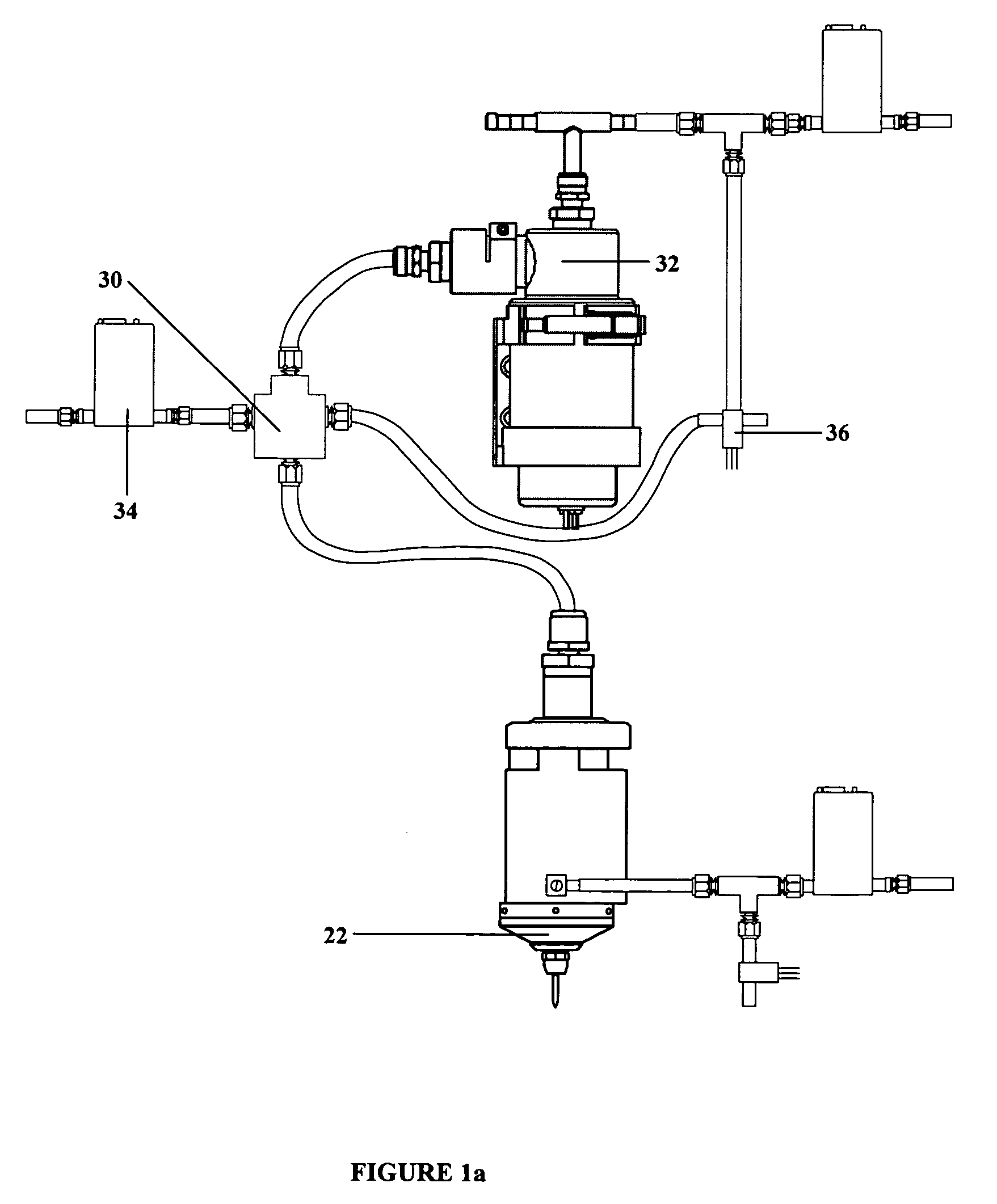
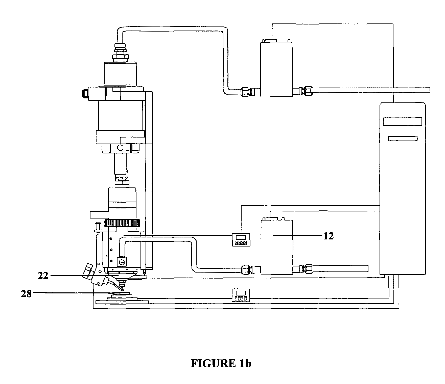
"The present invention is an apparatus and method for depositing a passive structure on a target with precise control over its properties. The apparatus includes an atomizer for creating an aerosol, an exhaust flow controller for removing excess carrier gas, a deposition head for entraining the aerosol in a cylindrical sheath gas flow, a pressure sensing transducer, and a cross-linked system for controlling the atomizer, deposition head, and exhaust flow controller. The method involves atomizing the material, entraining it in a carrier gas, removing excess carrier gas, monitoring the pressure, surrounding the aerosol with a sheath gas, and depositing it on the target. The apparatus and method can produce passive structures with tolerances of better than 5% for desired properties. The invention also includes a laser for measuring scattered light from a laser beam, which can be used to automatically control the atomizer power. Additionally, the invention provides a pre-processing treatment for the material in flight and long runtimes for the deposition apparatus."

Problems solved by technology

While thick film and thin film methods of passive structure fabrication are well-developed, these processes may be unsuitable for certain deposition applications.
Some disadvantages of thick film processes are the relatively large minimum linewidths that are characteristic of the technique, the need for mask utilization, and the need for high-temperature processing of the deposited material.
The disadvantages of typical thin film processes include the need to use masks, vacuum atmospheres, and multi-step photolithographic processes.
Indeed, the use of a virtual impactor in the invention disclosed therein eventually leads to failure of the system due to the accumulation of particles in the interior of the device.

Method used


Image

  • Aerodynamic jetting of aerosolized fluids for fabrication of passive structures
  • Aerodynamic jetting of aerosolized fluids for fabrication of passive structures
  • Aerodynamic jetting of aerosolized fluids for fabrication of passive structures

Examples


Embodiment Construction

Introduction and General Description

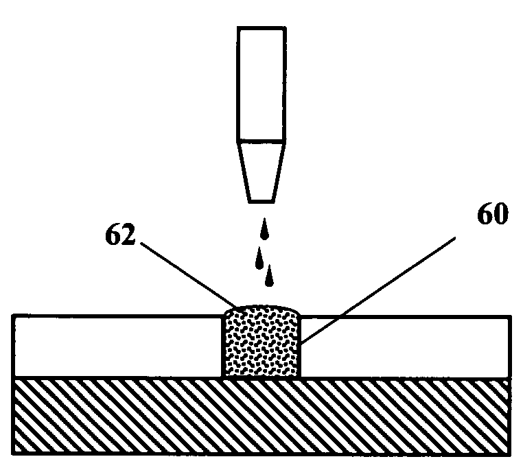
[0034]The M3D® process is an additive direct printing technology that operates in an ambient environment, and eliminates the need for lithographic or vacuum deposition techniques. The method is capable of depositing a passive electronic component in a predetermined pattern, and uses aerodynamic focusing of an aerosol stream to deposit patterns onto a planar or non-planar target without the use of masks or modified environments. The M3D® method is compatible with commercial thick film and polymer thick film paste compositions, and may also be used with liquid precursor-based formulations, particle-based formulations, and formulations consisting of a combination of particles and liquid precursors. The method is also capable of depositing multiple formulations onto the same target layer. This capability enables direct deposition of resistive structures with a large range of resistance values—ranging from under 50 Ω / square to over 500 KΩ / square—onto t...


PUM


Abstract

Method and apparatus for direct writing of passive structures having a tolerance of 5% or less in one or more physical, electrical, chemical, or optical properties. The present apparatus is capable of extended deposition times. The apparatus may be configured for unassisted operation and uses sensors and feedback loops to detect physical characteristics of the system to identify and maintain optimum process parameters.

Description

CROSS-REFERENCE TO RELATED APPLICATIONS[0001]This application claims the benefit of the filing of U.S. Provisional Patent Application Ser. No. 60 / 635,848, entitled “Solution-Based Aerosol Jetting of Passive Electronic Structures” filed on Dec. 13, 2004, and the specification thereof is incorporated herein by reference.BACKGROUND OF THE INVENTION[0002]1. Field of the Invention (Technical Field)[0003]The present invention relates generally to the field of direct deposition of passive structures. More specifically, the invention relates to the field of maskless, precision deposition of mesoscale passive structures onto planar or non-planar targets, with an emphasis on deposition of precision resistive structures.[0004]2. Background Art[0005]Note that the following discussion refers to a number of publications and references. Discussion of such publications herein is given for more complete background of the scientific principles and is not to be construed as an admission that such publ...

Claims


Application Information

Patent Timeline
Patent Type & Authority Patents(United States)
IPC IPC(8): H01L21/8234H10N30/074
CPCH01C17/06H01B13/0026B05D1/02H01C17/08H01L21/20H01L21/76804H01L21/76805H01L21/76877H01L21/76802H01L21/76879H10N30/074
Inventor RENN, MICHAEL J.ESSIEN, MARCELINOKING, BRUCE H.PAULSEN, JASON A.
Owner OPTOMEC DESIGN CO
Learn More