Automatic asynchronous signal pipelining

a technology of automatic asynchronous signal and pipeline register, which is applied in the direction of cad circuit design, pulse technique, instruments, etc., can solve problems such as circuit timing failure, and achieve the effects of reducing the worst-case delay of a distribution network, faster timing, and network speed

Inactive Publication Date: 2010-03-09
ALTERA CORP
View PDF1 Cites 13 Cited by
  • Summary
  • Abstract
  • Description
  • Claims
  • Application Information

AI Technical Summary

Benefits of technology

[0008]A third embodiment takes advantage of the possibility of using multiple distribution networks to distribute a single asynchronous signal to the user destination registers. This embodiment has an advantage over the first embodiment when the target device contains distribution networks that reach a strict subset of the device's resources. Typically, the worst-case delay of a distribution network decreases (i.e., the network becomes faster) as the area that is reachable by the distribution network is reduced. In this embodiment, the signal is routed from the asynchronous signal source to each of the selected distribution network buffers. Additionally, pipeline registers are inserted between the asynchronous signal source and each of the selected distribution network buffers. The connection between the asynchronous signal source and an arbitrary destination register is realized by selecting an appropriate distribution network that reaches that particular destination register. Since the delay of a distribution network that reaches a strict subset of the device is typically less than the delay of a chip-wide distribution network, faster timing may be achieved by inserting pipeline stages between the asynchronous source and the distribution network buffers. Alternatively, pipeline registers can also be inserted between the distribution network buffer and the destination registers.
[0009]A fourth embodiment takes advantage of beneficial skew in order to increase the utility of a distribution network. In this embodiment, beneficial skew is utilized by introducing a delay component that skews a clock signal to create a skewed clock signal. The skewed clock signal is used to clock, at least, a register just before the distribution network buffer. The result is a looser timing requirement from that register to the destination registers; but this can also result in a corresponding tighter timing requirement on any synchronous register-to-register transfers ending on the register feeding the distribution network buffer—unless the skewed clock signal also clocks the source registers of those transfers. Alternatively, pipeline registers can also be inserted between the distribution network buffer and the destination registers.
[0010]The technique has utility for, but not limited to, FPGA devices, structured ASIC devices, custom devices, and other types of programmable logic devices. The technique is useful for distribution of any type of asynchronous signal, especially the distribution of high-fanout signals across a substantial portion of a synchronous design, where the signal must reach all destinations within a single clock cycle. The technique is advantageous because an electronic design automation tool alters the netlist automatically without the need for a user to manually alter his or her design.

Problems solved by technology

A second embodiment is used when the delay from the distribution network buffer to the destination registers (subsequently referred to as the delay of the network) results in failed circuit timing.

Method used


Image

  • Automatic asynchronous signal pipelining
  • Automatic asynchronous signal pipelining
  • Automatic asynchronous signal pipelining

Examples


implementation example

Detailed Implementation Example

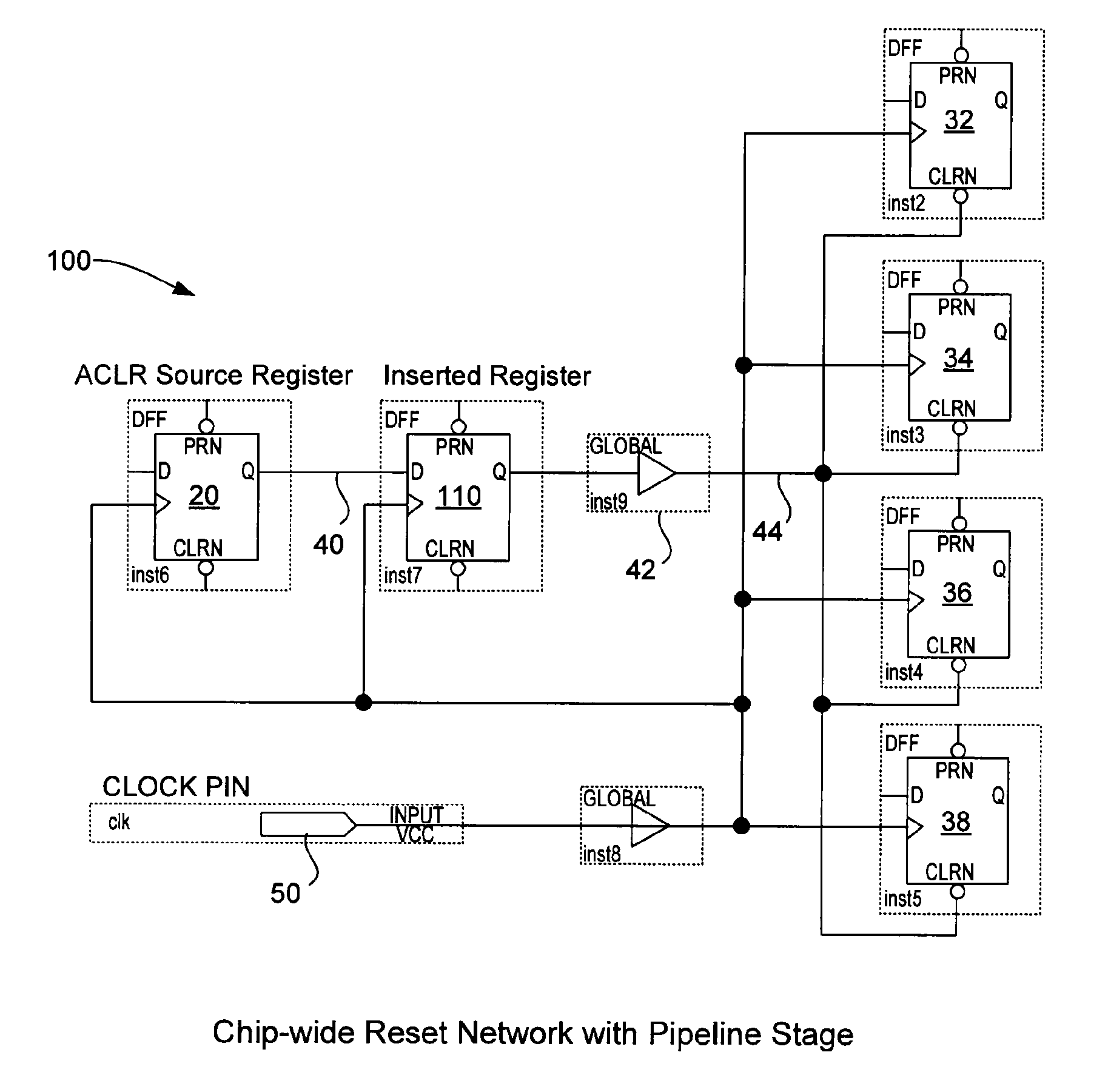
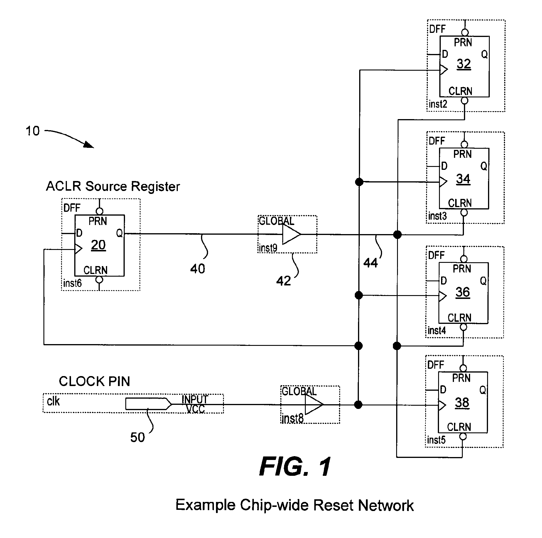
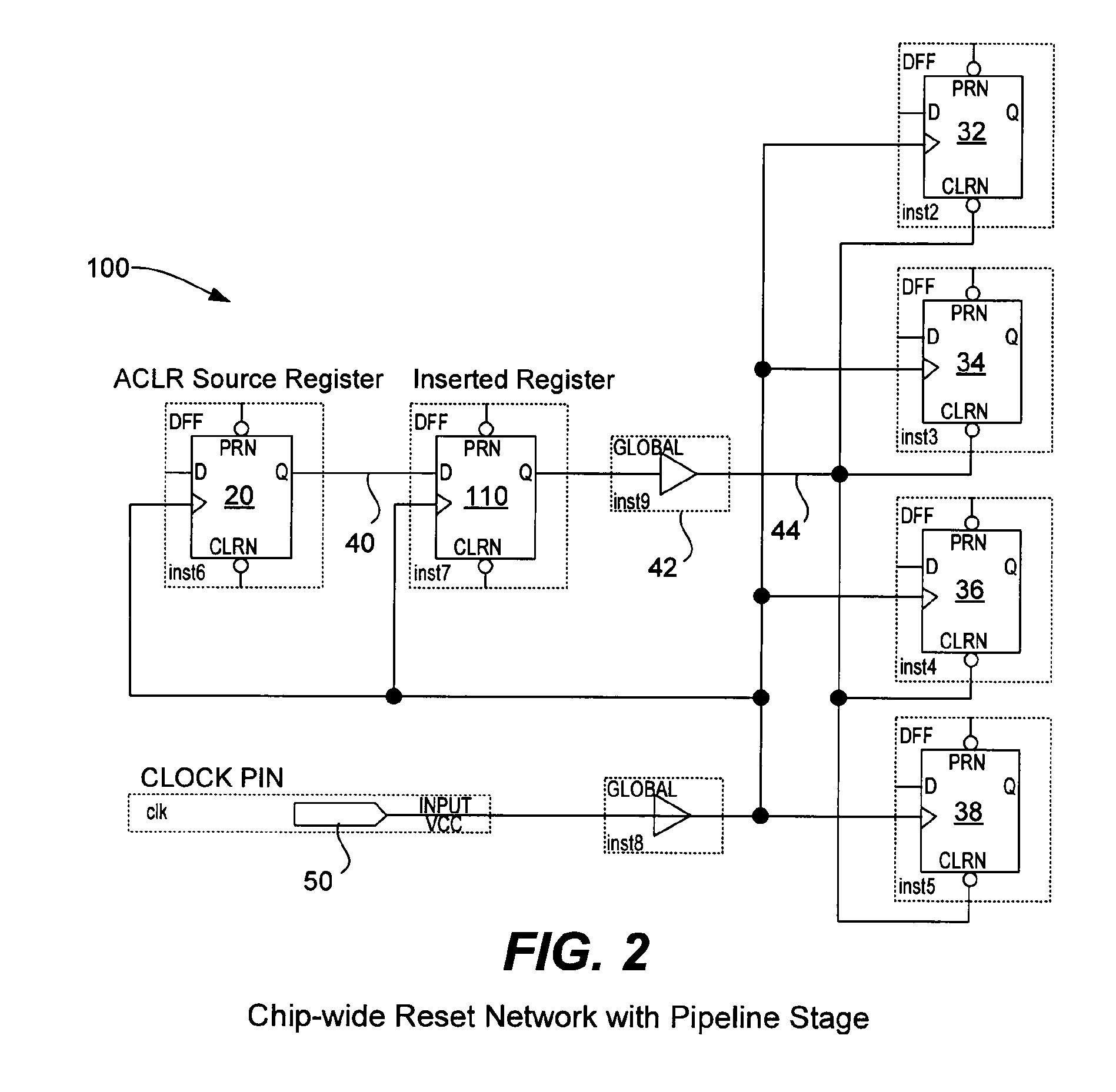
[0035]The following details assist the electronic design automation software in implementing the asynchronous signal pipelining technique described above by automatically altering the user's design to meet timing requirements. A number of high-level considerations are useful to keep in mind during implementation: 1) prefer algorithms that minimally perturb the user's design, 2) use intelligent optimization decisions given the logical equivalence of pipeline registers, and 3) ensure that all phases of the EDA tool are aware of the decisions made by the asynchronous signal pipelining technique. Electronic design automation software typically performs the steps of logic synthesis and fitting to compile a logic design. Fitting can include, but is not limited to, the following phases: 1) initial physical synthesis, 2) distribution network assignment, 3) placement, 4) post-placement physical synthesis, and 5) routing. Distribution network assignment is a pha...


PUM


Abstract

An electronic design automation (EDA) tool alters a user's netlist to provide timing success for distribution of asynchronous signals. Distribution networks are used with the addition of pipeline registers before and / or after the distribution buffer. Or, a tree of pipeline registers is inserted between the asynchronous source and the destination registers. Or, any number of distribution networks are stitched together and pipeline stages may be inserted before and / or after each distribution buffer. Or, beneficial skew is utilized by introducing a delay component that skews a clock signal. The skewed clock signal drives a pipeline register that is inserted before a distribution buffer in order to improve timing margin. Any of various compilation techniques may be used within the EDA tool to solve the problem of distributing high-speed, high-fanout asynchronous signals. The technique has utility for high-performance FPGAs and structured ASIC families, as well as for low-cost FPGAs and other types of logic devices.

Description

FIELD OF THE INVENTION[0001]The present invention relates generally to design of an integrated circuit. More specifically, the present invention relates to automatically inserting pipeline registers during compilation of a logic design.BACKGROUND OF THE INVENTION[0002]Various electronic design automation (EDA) tools are useful for automating the processes by which integrated circuits, multi-chip modules, boards, etc., are designed and manufactured. In particular, electronic design automation tools are useful in the design of standard integrated circuits, custom integrated circuits (e.g., ASICs), and in the design of custom configurations for programmable integrated circuits. Integrated circuits that may be programmable by a customer to produce a custom design for that customer include programmable logic devices (PLDs). Programmable logic devices refer to any integrated circuit that may be programmed to perform a desired function and include programmable logic arrays (PLAs), programm...

Claims


Application Information

Patent Timeline
Patent Type & Authority Patents(United States)
IPC IPC(8): G06F17/50
CPCG06F17/5054G06F17/5072G06F2217/84H03K19/17736H03K19/00323G06F30/34G06F30/392G06F2119/12G06F30/327G06F30/394G06F30/347G06F30/3947
Inventor BOURGEAULT, MARKFUNG, RYANLEWIS, DAVID
Owner ALTERA CORP
Why Eureka
Try Eureka