Velocity independent analyte characterization

Inactive Publication Date: 2010-03-16
CALIFORNIA INST OF TECH
View PDF71 Cites 120 Cited by
  • Summary
  • Abstract
  • Description
  • Claims
  • Application Information

AI Technical Summary

Benefits of technology

[0025]Preferably, the signals from the first and the second detection zones are averaged and normalized using the time difference. By averaging t

Problems solved by technology

This complicates measurement of analytes since each analyte, e.g., cell or molecule, passes through the interrogation region with a different velocity.
One can mitigate the effects of the Poiseulle flow by using a sheath fluid for hydrodynamic focusing, but this introduces other issues by diluting the sample and complicating downstream analysis.
Although electroosmotic flow is typically more uniform and plug-like than pressure driven flow, it too results in variability in flow velocity.
Furthermore, in some cases, it has also been shown that eukaryo

Method used


Image

  • Velocity independent analyte characterization
  • Velocity independent analyte characterization
  • Velocity independent analyte characterization

Examples


Example

EXAMPLE 1

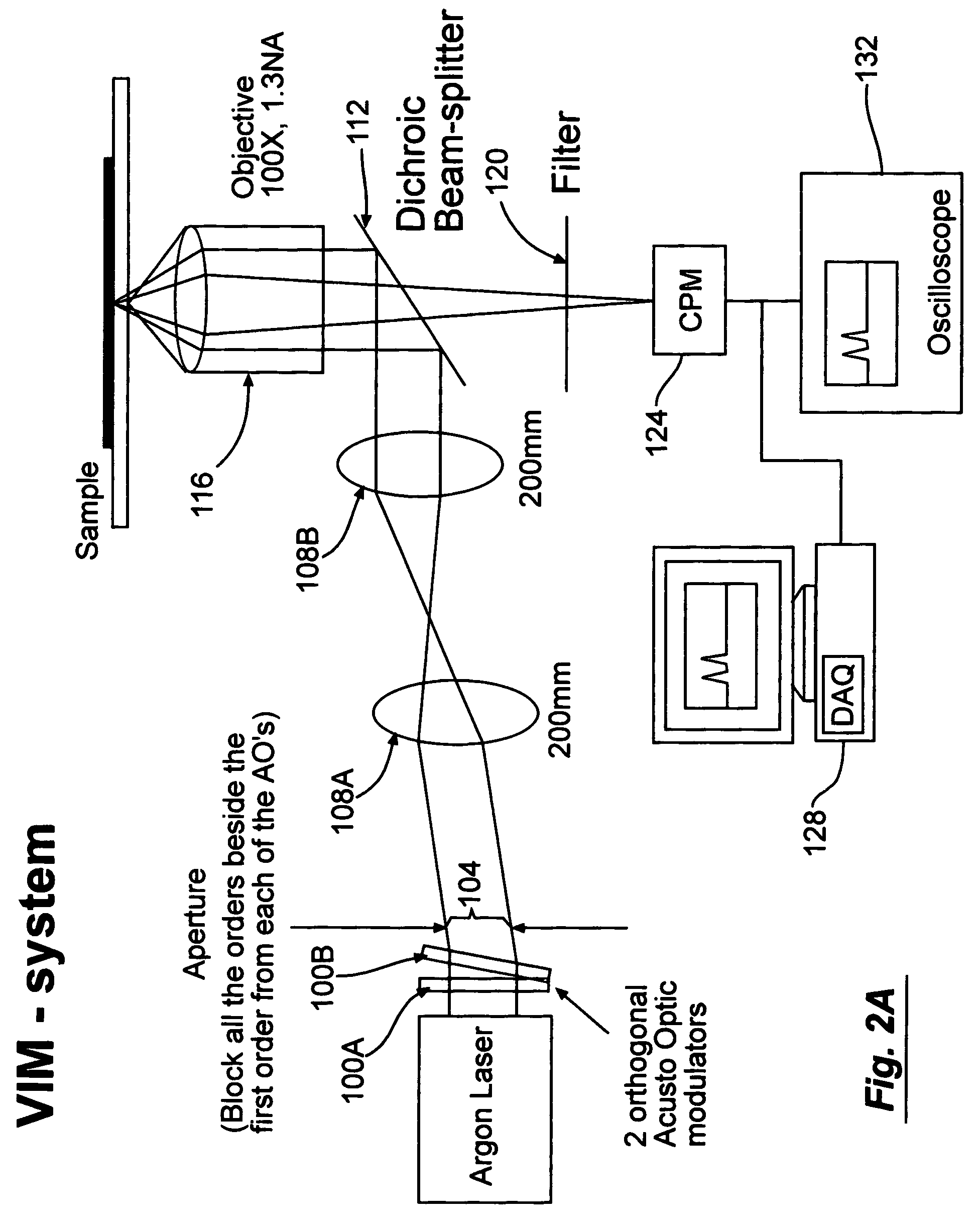
[0085]This example illustrates the method of measuring flow velocity of particles.

[0086]A solution of fluorescent beads (FluoSpheres Biotin Labeled microspheres 0.2 μm, yellow green fluorescent, Molecular Probes) were introduce into the microfluidic device and their velocity were measured. The flow of fluorescent beads was achieved by capillary flow in the microfabricated channels sealed by coverslips. A histogram of the bead flow velocities is seen in FIG. 5 for a later time in the experiment in which the transient stage is over and the velocity distribution become roughly constant. Assuming uniform distribution of beads in the channel, the theoretical probability, Ppr, of a particle with velocity ν0 to pass through the cross section in a given time is given by the equation:

[0087]Ppr⁡(v=v0)=v0⁢Pv⁡(v=v0)∫vPv⁢ⅆv

where Pν is the probability to have a velocity v in the cross section of the channel. In circular tubes Pν is constant for νmax for Poiseuille flow. The rectangular c...

Example

EXAMPLE 2

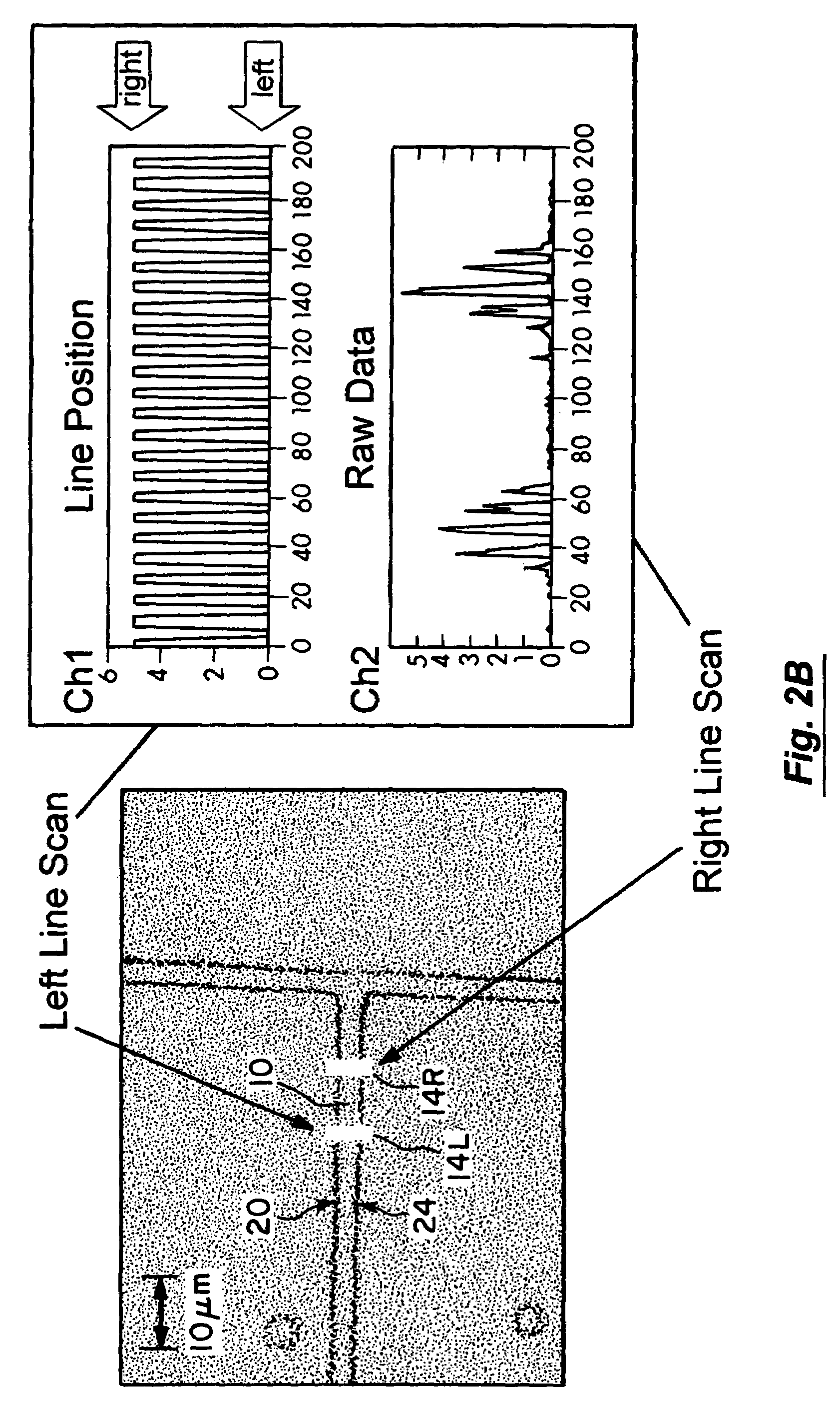
[0088]In the next experimental stage a solution of a mix of two kinds of beads (Component A and B, LinearFlow green flow cytometry intensity calibration kit, 2.5 μm, Molecular Probes) which were similar in every other aspect besides their fluorescent intensity was introduce to the system. The fluorescent intensity of the beads was collected by the channel photomultiplier for a period of 400 sec. For each passing particle, the normalized area and velocity were calculated.

[0089]The velocity as a function of time was plotted. See FIG. 4. The flow in the system is capillary flow and is driven by the pressure difference between the ends of the channel. During the time of the experiment, the pressure at the beginning of the channel, originating from the fluid at the starting basin, decreases while the pressure at the output increases. This pressure change results in a decay in the velocity over time, as shown in FIG. 4 (t>20 sec). The abrupt change in the velocity, which occurs a...

Example

EXAMPLE 3

[0092]Lambda phage DNA (GIBCO) was diluted in buffer (Tris EDTA, pH 6.8 with 5 mM NaCl) and stained with the intercalating dye C49H58I4N6O2, marketed as YOYO®-1 (Molecular Probes) at a stochiometry of one dye molecule per 4 bp.

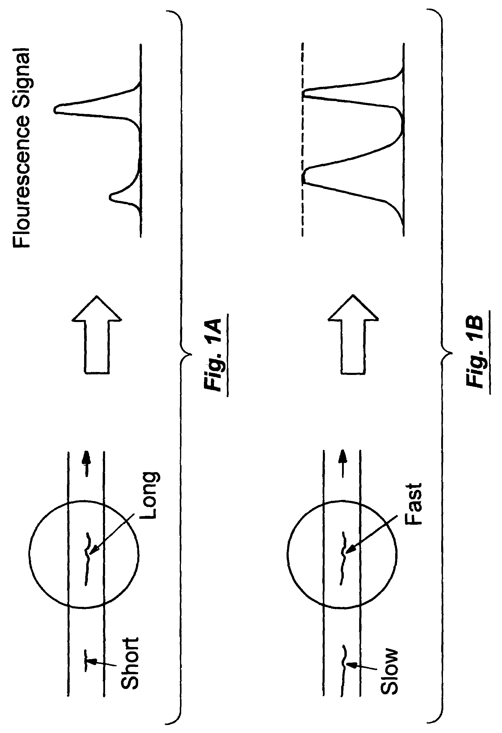
[0093]Then a solution of stained λ DNA was introduced to the microfluidic device for a period of 5 minutes. A histogram of the normalized areas of the molecules is plotted and is shown in FIG. 6. The center peak in the histogram corresponds with the λ DNA (48 kbp) and the small peak in the right corresponds with hybridized pairs of λ DNA (96 kbp), i.e., λ2. The CV for the λ and λ2 peaks were 8.34% and 7.61%, respectively, and the ratio between the centers of the two peaks was 2.06.

[0094]The foregoing discussion of the invention has been presented for purposes of illustration and description. The foregoing is not intended to limit the invention to the form or forms disclosed herein. Although the description of the invention has included description of ...


PUM


Abstract

The present invention provides apparatuses for determining velocity independent analyte characteristic parameters and methods for using the same. In one particular aspect, the present invention provides a velocity independent flow cytometry.

Description

CROSS-REFERENCE TO RELATED APPLICATIONS[0001]This application claims the benefit of U.S. Provisional Application No. 60 / 237,937, filed Oct. 3, 2000, which is incorporated herein by reference in it entirety.STATEMENT REGARDING FEDERALLY SPONSORED RESEARCH[0002]The U.S. Government has a paid-up license in this invention and the right in limited circumstances to require the patent owner to license others on reasonable terms as provided for by the terms of Grant No. HG-01642-02, awarded by the National Institute of Health.FIELD OF THE INVENTION[0003]The present invention relates to an apparatus and a method for determining a characteristic parameter of an analyte in a fluid medium. In one particular aspect, the present invention relates to a velocity independent flow cytometry.BACKGROUND OF THE INVENTION[0004]Recently, there has been a growing interest in microfluidic flow cytometry. Several chip based systems have been demonstrated for cytometry and sorting of cells and molecules. See,...

Claims


Application Information

Patent Timeline
IPC IPC(8): G01N33/53B01L3/00B81B1/00B81B3/00F04B19/00F04B43/04G01N15/10G01N15/14G01N30/20G01N30/32G01N30/60
CPCB01L3/5027F04B19/006F04B43/043B01L2200/0647G01N15/1468G01N15/147G01N15/1484G01N30/6095G01N2015/1006G01N2015/1438G01N2015/149G01N2030/205G01N2030/322F04B43/14G01N33/53
Inventor EYAL, SHULAMITQUAKE, STEPHEN
Owner CALIFORNIA INST OF TECH
Why Eureka
Try Eureka