Rolling assembly and pick assembly mounted on a trencher

a technology of pick assembly and trencher, which is applied in the direction of slitting machines, agriculture tools and machines, construction, etc., can solve the problems of degrading the wave formation left by the roller assembly, and achieve the effect of extending the life of the pick assembly and reducing the wear of the roller assembly

Active Publication Date: 2010-03-23
NOVATEK IP +1
View PDF20 Cites 42 Cited by
  • Summary
  • Abstract
  • Description
  • Claims
  • Application Information

AI Technical Summary

Benefits of technology

[0008]The roller assembly may leave waves or groves in the formation during the trenching process and the pick assembly may be adapted to break any grove or wave left by the roller assembly. The pick assembly may be disposed in a holder that comprises a taper adapted to pass through the formation. The taper may increase from a bottom portion of the pick assembly. The pick assembly and the roller assembly may be bolted, welded, or combination thereof to the chain driven assembly. The pick assembly may further comprise a spring mechanism, which may aid in extending the life of the pick assembly. The roller assembly and the pick assembly may be attached to a link of the chain driven assembly with the pick assembly comprising a positive or negative rake angle. In some embodiments the roller assembly may be offset in direction relative to the link.
[0009]The pick assembly may comprise a superhard material selected from the group consisting of cubic boron nitride, diamond, diamond like material, or combinations thereof and may be disposed posterior the roller assembly. The pick assembly may further comprise a bottom portion opposite an end with a pointed geometry with a space intermediate the bottom portion and the holder. The pick assembly may also rotate within the holder. This may aid in resisting wear to a single portion of the pick assembly. The pick assembly may also comprise a lubrication system which may aid in resisting wear to the pick assembly. The roller assembly may also comprise a lubrication system adapted to reduce wear to the roller assembly. The chain driven assembly may comprise a plurality of roller assemblies that may comprise a roller assembly with a different number of pointed inserts than another roller assembly.

Problems solved by technology

The pick assembly comprising a shear cutter or a pointed geometry may degrade the wave formation left by the roller assembly.

Method used


Image

  • Rolling assembly and pick assembly mounted on a trencher
  • Rolling assembly and pick assembly mounted on a trencher
  • Rolling assembly and pick assembly mounted on a trencher

Examples


Embodiment Construction

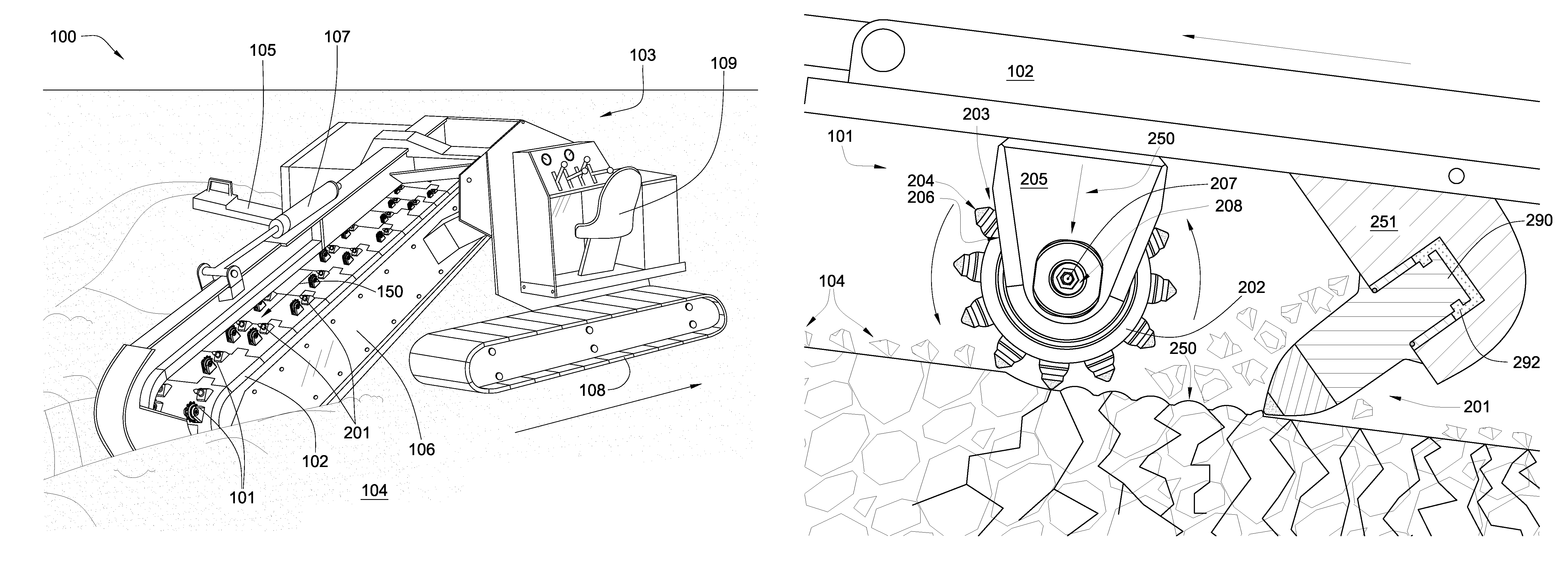
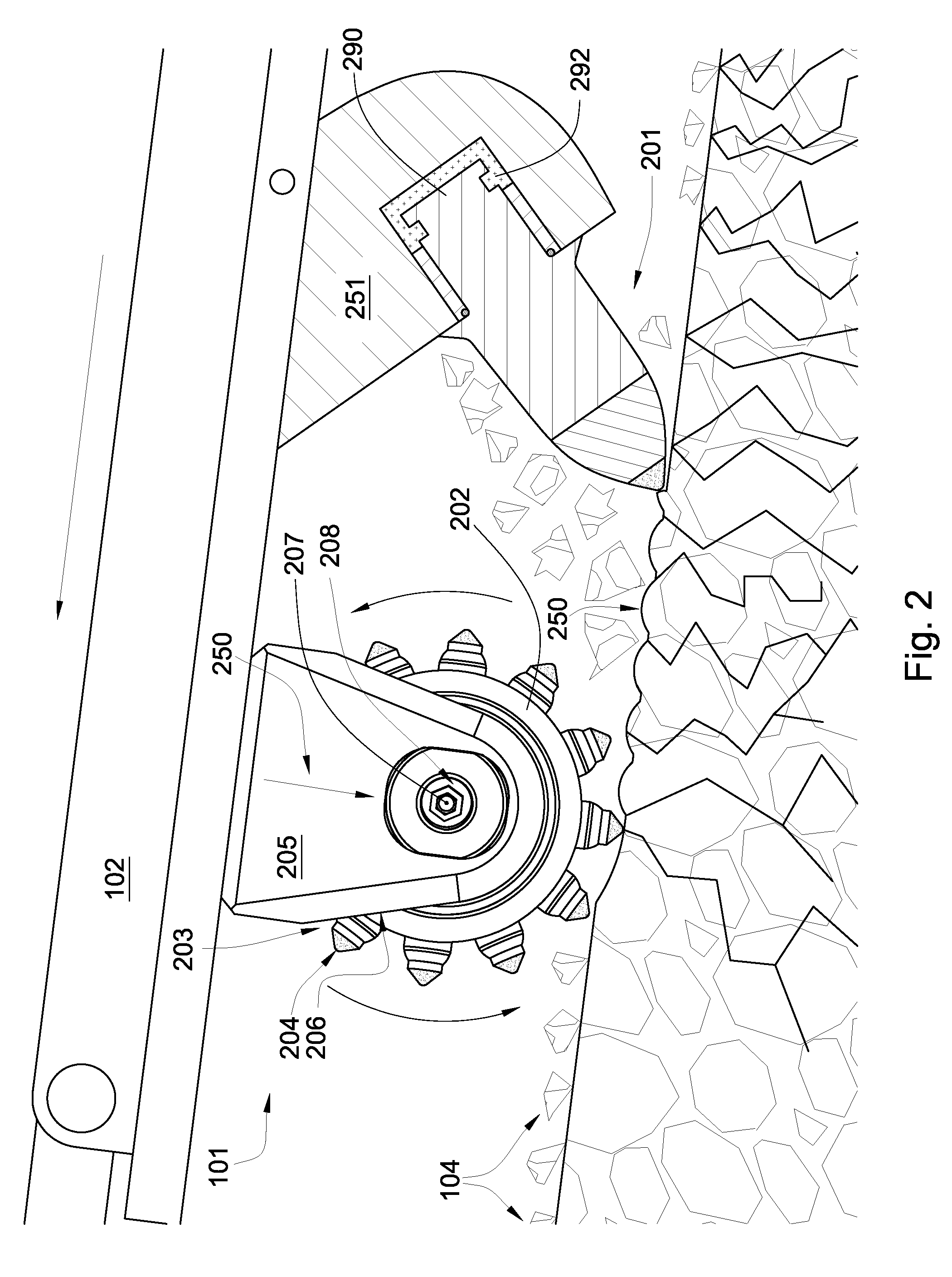
[0024]FIG. 1 is a perspective diagram of an embodiment of a trenching machine 100. FIG. 1 shows a plurality of roller assemblies 101 on a chain driven assembly 102 attached to a motor vehicle 103. The plurality of roller assemblies 101 may be exteriorly mounted in a “V” pattern on the chain 102 to facilitate degradation and removal of a formation 104. Posterior the roller assembly may be a pick assembly 201 to facilitate degradation of the formation 104. The rotating chain 102 rotates in the direction of the arrow 150 and cuts the formation 104 forming a trench while bringing the formation 104 cuttings out of the trench to a conveyor belt 105 which directs the cuttings to a side of the trench. The chain driven assembly 102 is supported by an arm 106. The arm 106 may be raised while the trenching machine 100 is being transported or it may be lowered for trenching as shown in FIG. 1. The position of the arm 106 may be controlled by a hydraulic piston and cylinder 107. The trenching ma...


PUM

PropertyMeasurementUnit
thicknessaaaaaaaaaa
thicknessaaaaaaaaaa
thicknessaaaaaaaaaa

Abstract

In one aspect of the present invention, a roller assembly on an excavator for degrading natural and man-made formations has a plurality of pointed inserts disposed along its outer diameter. The inserts have a tip adapted to impact the formation and at least one of the tips has polycrystalline diamond bonded to a cemented metal carbide segment. The diamond also has a substantially conical geometry with a 0.50 to 0.200 inch radius and a thickness greater that 100 inches at the apex. The diamond also has a volume that is 75 to 150 percent of a volume of a carbide substrate.

Description

CROSS REFERENCE TO RELATED APPLICATIONS[0001]This application is a continuation in-part of U.S. patent application Ser. No. 11 / 748,184 which was filed on May 14, 2007 and is herein incorporated by reference for all that it discloses.[0002]This application is also a continuation-in-part of U.S. patent application Ser. No. 11 / 673,634 which was filed on Feb. 12, 2007 and is herein incorporated by reference for all that it discloses.BACKGROUND OF THE INVENTION[0003]In the trenching industry, earth may be degraded using picks or teeth to break up minerals and rocks. Picks are generally attached to chain driven assemblies and are used for excavating large amounts of hard materials. In trenching, a chain supporting an array of picks may rotate such that the picks engage a surface causing it to break up.[0004]Examples of degradation assemblies from the prior art are disclosed in U.S. Pat. No. 6,824,225 to Stiffler, which is herein incorporated by reference for all that is contains discloses...

Claims


Application Information

Patent Timeline
Patent Type & Authority Patents(United States)
IPC IPC(8): E02F5/02
CPCE02F3/10E02F3/142E02F3/20E02F5/06E02F5/08E02F9/2866E21C27/24
Inventor HALL, DAVID R.CROCKETT, RONALDTOBIAS, SIGMAR
Owner NOVATEK IP
Why Eureka
Try Eureka