Concrete composite wall panel

a composite wall panel and concrete technology, applied in the field of insulated walls, can solve the problems of destructive damage to the exterior facing, and achieve the effects of reducing the risk of damage, and resisting deflection

Inactive Publication Date: 2010-03-23
RUBIO EDWARD
View PDF15 Cites 38 Cited by
  • Summary
  • Abstract
  • Description
  • Claims
  • Application Information

AI Technical Summary

Benefits of technology

[0005]This present invention provides a load bearing exterior wall based on metal framing encased in foam core having an exterior composite surface of concrete embedded in reinforcing mesh attached to the frame, and an interior surface of a concrete composite or conventional facing. The wall uses the framing and masonry skills and tools of current personnel and enables construction in a manufacturing facility for savings in time and labor. The exterior walls are formed of multiple panels with framed openings for doors and windows and can be transported to the construction site for erection. The foam core is formed of a polymeric foam block, preferably expanded polystyrene, having vertical slots formed therein providing conformal pockets for telescopic insertion of metal C-studs. The slot surfaces abut the entire periphery of the studs thereby resisting deflection along the stud length and increasing the load bearing strength. Spaced slots are formed in the top and bottom of the core for receiving framing tracks attached to the studs conventionally by fasteners and forming the upper and lower frame walls for attachment to adjacent building structure. The tracks may be an extending length for assembling multiple panels. Door and window openings are formed with conventional framing members and the foam removed from the openings. The studs are thus spaced from the outer core surface by foams, providing thermal breaks and increasing the R-value of the wall.
[0006]A concrete reinforcing mesh is attached by headed fasteners against the foam core and mechanically to the side walls of the studs at the exterior surface and optionally the inner surface. Preferably, assembly to this stage is done in a factory setting to maximize construction efficiency and cost. The panel is placed on a horizontal work surface and the panel perimeter dammed with concrete forms. Concrete is applied to the surface to a depth embedding the mesh and bonding to the core surface thus providing a composite layer further increasing wall strength. If a concrete facing is desired on the interior surface, after curing of the exterior concrete layer, the panel is inverted and the process repeated on the interior side. The interior surface conventionally applied after erection. The complete wall section is lighter in weight than masonry walls and may be hoisted into place by light weight lifting equipment. The completed exterior has superior resistance to environmental conditions including hurricane force winds and rain, seismic waves, insects infestation, salt spray, moisture intrusion, acoustical transmission, and the like as well as superior fire resistance.
[0007]Accordingly, it is an object of the invention to provide an improved exterior wall panel with improved strength and insulation with a composite exterior layer of concrete.
[0009]A further object is to provide an exterior load bearing material of improved strength and insulation using conventional materials and skills for construction.

Problems solved by technology

Further, the exterior facings are subject to destructive damage under extreme climate conditions including hurricanes, blizzards, tornadoes and the like.

Method used


Image

  • Concrete composite wall panel
  • Concrete composite wall panel
  • Concrete composite wall panel

Examples


Embodiment Construction

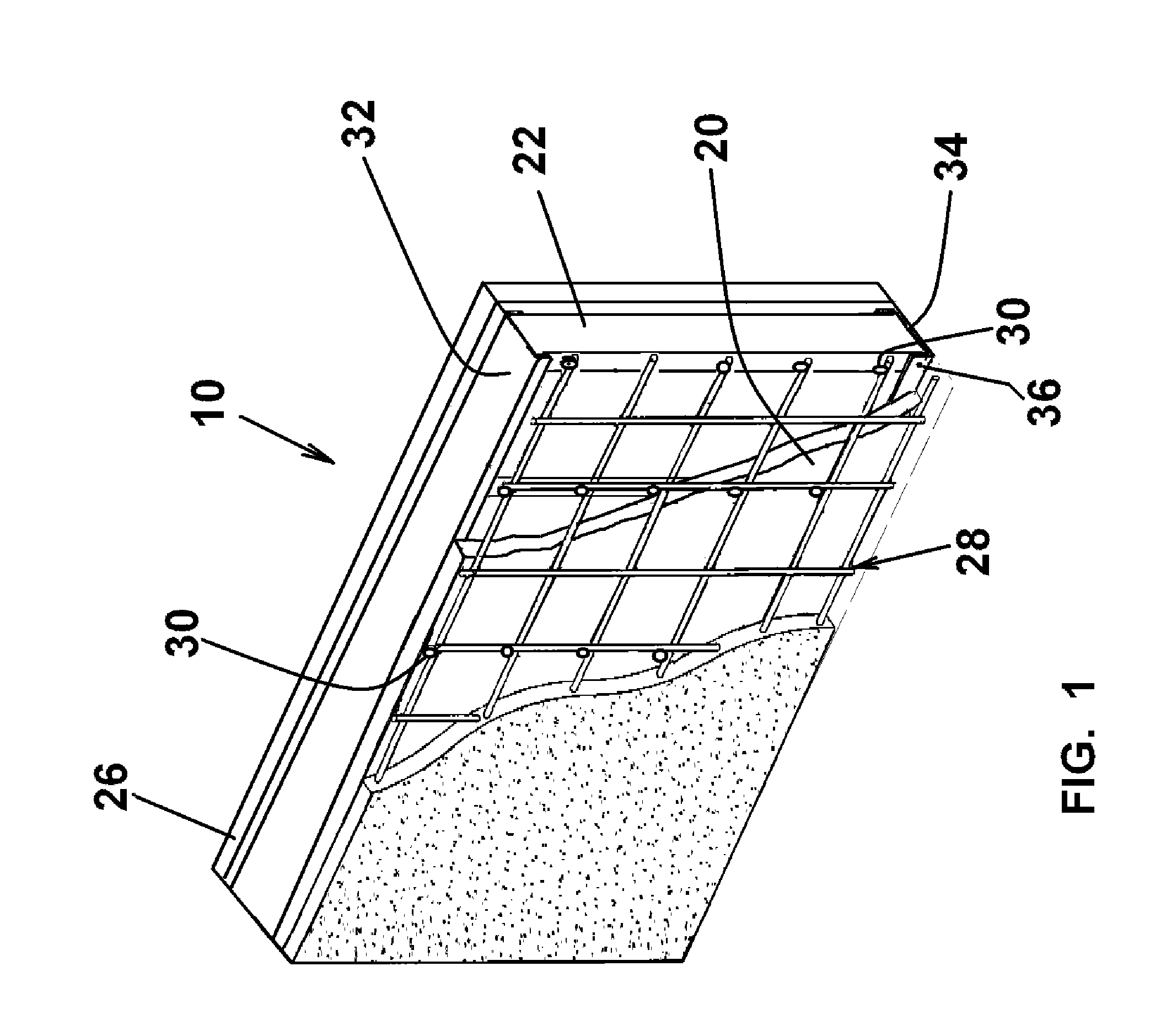
[0020]Referring to FIG. 1, there is shown a concrete composite wall panel 10 for an exterior wall of a structure, such as a residential or commercial building. As described below, the panel 10 is assembled with other panels to form the perimeter of the structure. These panels are provided with openings for doors, windows and the like as shown in FIG. 7 as described below. The panels may be of varying width, typically in 2 or 4 foot increments, and assembled at conventional joints to adjacent panels to form an extended wall section.

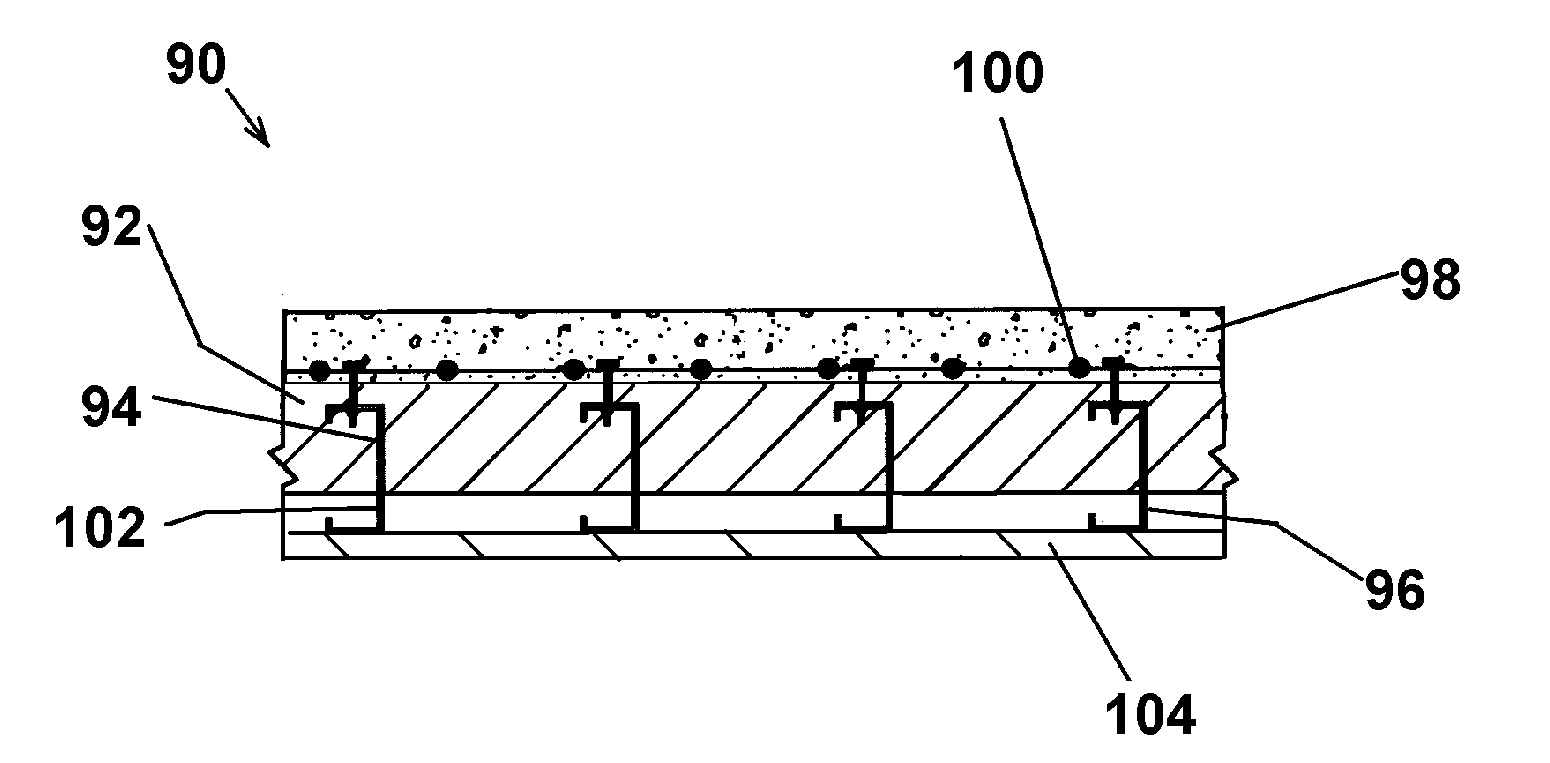
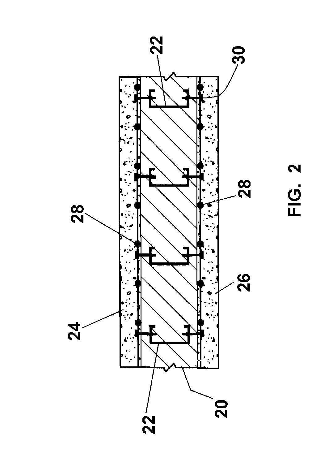
[0021]The composite panel 10 comprises a foam insulation core 20 carrying vertical support members such as C-studs 22 in internal pockets and having precast exterior and interior concrete facings 24, 26, respectively, bonded on the outer surfaces and anchored in a wire mesh 28 attached to the studs 22 by fastener assemblies 30. The panels are laterally placed side to side and interconnected with upper and lower U-shaped channel or tracks 32, 34 retained in...


PUM


Abstract

A composite wall panel for exterior walls of a structure includes a polymeric foam core having a C-stud framing system embedded therein and an exterior and / or interior facing formed of a reinforced concrete bonded to the core surface and mechanically attached to the studs thereby providing increased strength, insulation and resistance to environmental conditions.

Description

FIELD OF THE INVENTION[0001]The present invention relates to insulated walls and, in particular, to a concrete faced insulated wall panel for load bearing exterior building walls.BACKGROUND OF THE INVENTION[0002]Exterior load bearing walls for residential and commercial structures generally comprise field built framing, wood or steel, to which an exterior facing such as wood, vinyl or aluminum siding, brick or masonry veneer is field applied. After insulating the frame cavities, an interior facing is also field applied. The materials for such construction and the tools and the skilled personnel for erection are readily available. While hybrid walls have been proposed, the industry has been resistant to change.[0003]The load bearing strength of such walls is based entirely on the framing members in accordance with applicable codes with the contribution of the other wall components not taken into account, thus dictating wall thickness. The wall thickness in turn limits the insulation ...

Claims


Application Information

Patent Timeline
Patent Type & Authority Patents(United States)
IPC IPC(8): E04C2/04
CPCE04C2/044
Inventor RUBIO, EDWARD
Owner RUBIO EDWARD
Why Eureka
Try Eureka