Suspension gimbal designs with better dynamic performances

a technology of suspension gimbal and dynamic performance, which is applied in the direction of maintaining head carrier alignment, recording information storage, instruments, etc., can solve the problems of adversely affecting the dynamic performance of the suspension, and poor dynamic performance of many existing suspensions, so as to minimize the stress in the traces. , the effect of sufficient length

Active Publication Date: 2010-03-23
SAE MAGNETICS (HK) LTD
View PDF6 Cites 6 Cited by
  • Summary
  • Abstract
  • Description
  • Claims
  • Application Information

AI Technical Summary

Benefits of technology

[0021]The first object of the present invention is to provide a gimbal design for a slider mounted read / write transducer (referred to hereinafter as a slider) that optimizes the suspension's dynamic response, or, in other words, minimizes adverse contributions of the suspension, to slider motion over an air bearing layer.
[0022]The second object of the present invention is to provide a gimbal design for a slider that has minimal adverse effects on the dynamic response of a suspension to HDI events.
[0023]The third object of the present invention is to provide such a dynamically optimized gimbal design that does not degrade already acceptable static slider properties such as stiffness in response to pitch, roll and radial motion.
[0024]The fourth object of the present invention is to provide such a dynamically optimized gimbal design that makes use of and even improves upon such existing gimbal design features as the shape of the ramp limiter, the routing of traces, the stresses on solder ball connections to slider terminals and the heat dissipation properties of the gimbal during the solder ball melting process.
[0028]3) appropriate routing and support of the traces relative to the connecting bars and the solder ball connections, the routing minimizing overlap of the traces with the stainless steel structure of the gimbal and the routing being of sufficient length so as to minimize stresses in the traces and on the solder connections to the slider.
[0029]The gimbal designs that incorporate these features have been shown to produce the dynamic performance of the suspension that meets the objects of the invention.

Problems solved by technology

In general, dynamic performance requirements are not always enforced, so the dynamic performance of many existing suspensions is not good.
In this regard, there are elements of the gimbal structure that are meant to provide improved static performance of the suspension system, but their design can have an adverse impact on the dynamic performance of the suspension.
It is discovered, however, that the manner in which the traces are laid out and the route along which they are laid out also affects the dynamic performance of the suspension.
Those modes at low frequencies (eg. between 20 and 100 kHz) that are not well damped make it difficult for the slider to relax to an equilibrium condition.
They can even cause the air bearing condition to become unstable and generate a sustained vibration of the slider.
Under such circumstances the disk drive will fail or, at the least, its performance will be seriously degraded.
As is clearly shown, the modes are narrow and sharp, indicating very little damping, and the fact that they are at low frequencies (below 100 kHz) is evidence that more damaging effects may occur.
The gimbal design does not address problems of suspension dynamics, however.
It is not a mechanism that is meant to prevent such shocks from occurring.
This design does not address the problem of gimbal dynamics during operation of the HDD.

Method used


Image

  • Suspension gimbal designs with better dynamic performances
  • Suspension gimbal designs with better dynamic performances
  • Suspension gimbal designs with better dynamic performances

Examples


Embodiment Construction

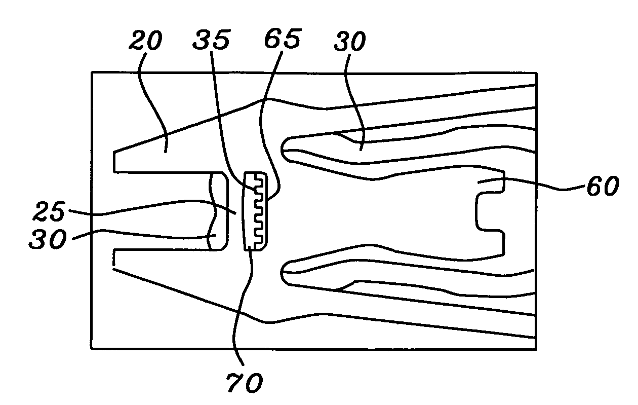
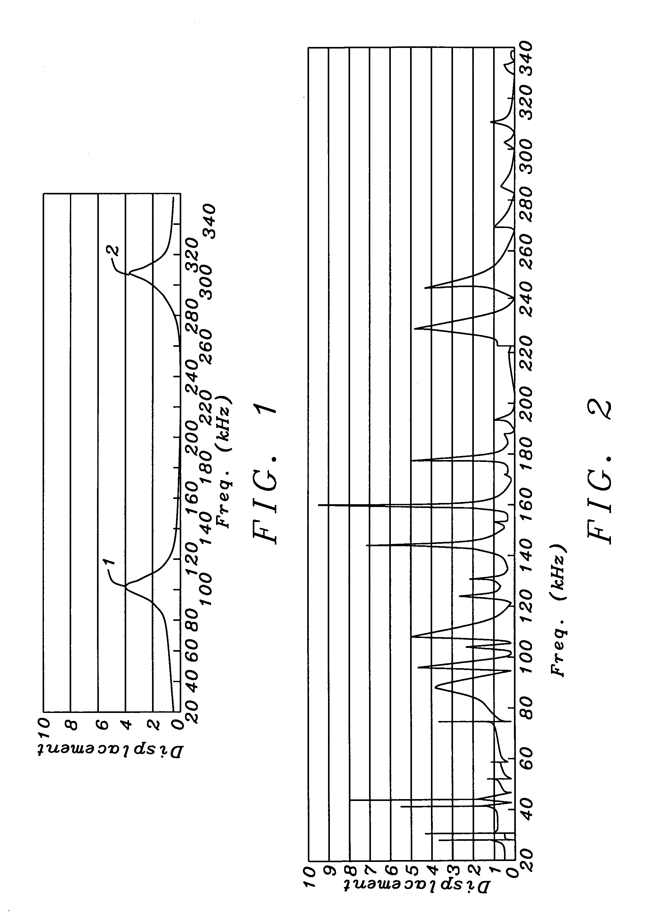
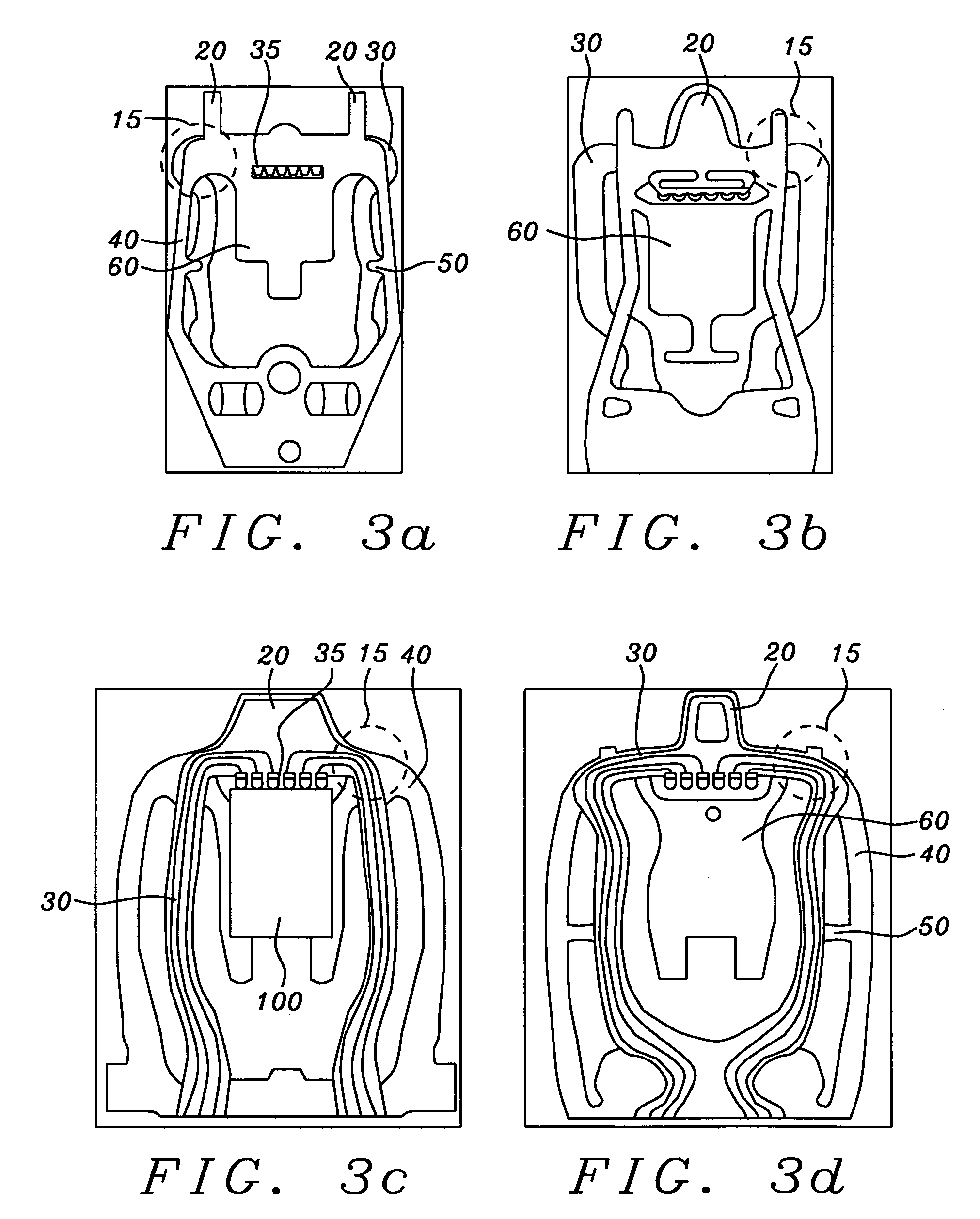
[0042]Each preferred embodiment of the present invention is a gimbal design that produces improved / optimized dynamic response of a slider mounted thereon (and with the gimbal being a part of a suspension) as compared to the slider response when mounted on a prior art gimbal / suspension. Such improved dynamic response can be observed, for example, in the shape and frequency dependence of the vibrational modes of the gimbal mounted slider subsequent to a HDI interaction between the slider and a disk surface asperity and / or lubricant on a rotating disk. It might, in fact, be more correct to say that the design of a gimbal should be to minimize adverse effects on the dynamics of the suspension and that such a minimization can be equated to an improvement of suspension dynamics. It is precisely these effects that the embodiments of the present invention will produce. It is noted that within the context of the following description, “distal” refers to the slider end of the gimbal, “proxima...


PUM

PropertyMeasurementUnit
heightaaaaaaaaaa
frequenciesaaaaaaaaaa

Abstract

Gimbal designs are provided that minimize adverse dynamic performance of a HDD suspension, particularly subsequent to head-disk-interface (HDI) interactions. The improvement of operational performance can be seen in graphical representations of the vibrational modes of a gimbal mounted slider subsequent to such HDI interactions. Each gimbal design includes a ramp limiter formed as two separated arms connected by one or two transverse bars and a routing of conducting traces that relieves stress and minimally contacts these bars.

Description

BACKGROUND OF THE INVENTION[0001]1. Field of the Invention[0002]This invention relates to the design of a hard disk drive (HDD) suspension to support a slider mounted read / write transducer. More particularly, it relates to the design of a gimbal that provides superior dynamic performance during drive operation.[0003]2. Description of the Related Art[0004]A hard disk drive (HDD) uses an encapsulated thin film magnetic read / write head (transducer), called a slider, to read and write data on a magnetic medium or storage disk. The slider has a pre-patterned air-bearing surface (ABS) and is mounted on a flexible head gimbal assembly (HGA) that is itself mounted on a loadbeam. The combination of the loadbeam, the gimbal assembly (also referred to as a flexure), electrically conducting leads (or traces) that are routed along the gimbal and connect the slider to external circuitry (typically a pre-amplifier), a hinge mechanism and a baseplate, is collectively termed the suspension. The susp...

Claims


Application Information

Patent Timeline
Patent Type & Authority Patents(United States)
IPC IPC(8): G11B5/54G11B21/22
CPCG11B5/4826G11B21/02G11B21/16
Inventor ZENG, QINGHUAYANG, CHAO-HUIFU, YENCHA, ELLIS
Owner SAE MAGNETICS (HK) LTD
Why Eureka
Try Eureka