Method of controlling variable valve timing system, controller, and motorcycle including controller

a timing system and variable valve technology, applied in the direction of valve details, valve arrangements, valve drives, etc., can solve the problems of difficult to control the gain correctly, likely to occur overshooting, etc., and achieve the effect of reducing deviation and suppressing the occurrence of overshooting

Inactive Publication Date: 2010-03-30
KAWASAKI HEAVY IND LTD
View PDF9 Cites 6 Cited by
  • Summary
  • Abstract
  • Description
  • Claims
  • Application Information

AI Technical Summary

Benefits of technology

[0007]Accordingly, an object of the present invention is to provide a method of controlling a variable valve timing system, a controller, and a motorcycle comprising the controller, which are capable of suppressing occurrence of overshooting or of reducing a deviation with a relatively easy method and configuration regardless of viscosity change of a hydraulic oil or a mechanical manufacturing error.
[0009]In this configuration, the operation of the variable valve timing system can be suitably controlled so as to suppress occurrence of overshooting or to reduce a deviation with a relatively easy method. To be specific, primary advantages of high responsiveness to change of the target value of the position of the displacing member and suppressing of occurrence of overshooting can be achieved by the sliding mode control. In addition to this, the deviation can be reduced by the integral control. Furthermore, since the integration operation is executed only when a deviation between the target value and a current value falls within a predetermined numeric value range containing a zero value, i.e., only when the deviation has a relatively small value, suitable control is accomplished without degrading the advantage of the sliding mode control that occurrence of overshooting is suppressed while reducing the deviation.
[0011]Thereby, with a relatively simple configuration, the operation of the variable valve timing system can be controlled so as to suppress the occurrence of overshooting, reduce the deviation, and achieve high responsiveness as described above.
[0013]Thereby, a suitable second control amount is gained in the integral control calculator, and the advantage of the sliding mode control that overshooting is suppressed can be maintained while reducing the deviation.
[0015]Thereby, with a relatively simple configuration as described above, the variable valve timing system can be controlled so as to suppress occurrence of overshooting, reduce the deviation, and achieve high responsiveness so that running ability of the engine can be improved.

Problems solved by technology

However, in the hydraulic variable valve timing system subjected to the PI control, overshooting is likely to occur.
In contrast, in a hydraulic variable valve timing system subjected to proportional control, due to a viscosity change of the hydraulic oil which may occur with a temperature change, mechanical manufacturing errors of the variable valve timing system or the oil control valve, etc., a deviation will result from the event that a position of the rotor has converged before reaching a target value.
But, it is not easy to control the gain correctly.

Method used


Image

  • Method of controlling variable valve timing system, controller, and motorcycle including controller
  • Method of controlling variable valve timing system, controller, and motorcycle including controller
  • Method of controlling variable valve timing system, controller, and motorcycle including controller

Examples


Embodiment Construction

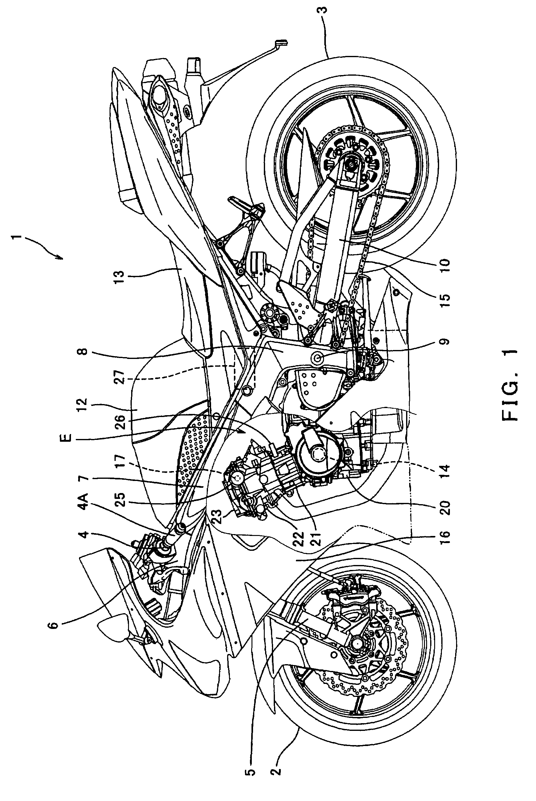
[0027]Now, a method of controlling a variable valve timing system, a controller, and a motorcycle comprising the controller, according to an embodiment of the present invention will be described with reference to the accompanying drawings. FIG. 1 is a left side view of a motorcycle of a road sport type comprising an engine E equipped with a variable valve timing system according to an embodiment of the present invention. As used herein, the term “direction” refers to directions from the perspective of a rider (not shown) straddling a motorcycle 1 of FIG. 1, except for a case specifically illustrated.

[0028]Turning now to FIG. 1, the motorcycle 1 includes a front wheel 2 and a rear wheel 3. The front wheel 2 is rotatably mounted to a lower end portion of a front fork 5 extending substantially vertically. The front fork 5 is mounted to a steering shaft (not shown) by an upper bracket (not shown) provided at an upper end portion thereof and an under bracket (not shown) provided under th...


PUM


Abstract

A method of controlling a variable valve timing system comprising calculating, by a sliding mode control, a first control amount based on a deviation between a target value and an actually measured value of the position of the displacing member of the variable valve timing system, calculating a second control amount by integrating the deviation as an input when the deviation falls within a predetermined numeric value range containing a zero value, or by integrating the zero value as the input when the deviation falls outside the predetermined numeric value range; and adding the first control amount and the second control amount to set a compensation control amount for compensating the position of the displacing member.

Description

TECHNICAL FIELD[0001]The present invention relates to a method of controlling a variable valve timing system configured to change a rotational phase of a camshaft with respect to a crankshaft, a controller, and a motorcycle comprising the controller.BACKGROUND ART[0002]For example, an engine mounted in a motorcycle is configured in such a manner that a crankshaft and a camshaft are rotatable in association with each other via a rotation transmission mechanism such as a chain and sprockets, and an intake valve and an exhaust valve are driven to be opened and closed at specified timings by a cam mounted to the camshaft. To be specific, the cam has a unique profile, and causes each valve to be opened and closed by predetermined opening and closing degrees at specified opening and closing timings, according to the profile. When the intake valve is opened, an air-fuel mixture is suctioned into a combustion chamber of the engine. The air-fuel mixture is compressed by a piston, and is ther...

Claims


Application Information

Patent Timeline
Patent Type & Authority Patents(United States)
IPC IPC(8): F01L1/34
CPCF01L1/3442F01L2001/34426F01L2001/3444F01L2800/00F01L2820/02
Inventor MATSUSHIMA, HIROHIDEFUKAMI, YOJIIKEDA, TAKESHISUZUKI, KOZO
Owner KAWASAKI HEAVY IND LTD
Why Eureka
Try Eureka