
Retractable curved air dam

a technology of air dam and curved axis, which is applied in the direction of roofs, heating types, lighting and heating apparatus, etc., can solve the problems of limiting the extent to which the air dam can yield, damage to the air dam fixedly suspended from underneath the front-end structure of the vehicle, etc., to improve the aerodynamic characteristics of the motor vehicle, fold back or yield, and increase the fuel economy. or vehicle range

Inactive Publication Date: 2010-03-30
GM GLOBAL TECH OPERATIONS LLC
View PDF19 Cites 16 Cited by
  • Summary
  • Abstract
  • Description
  • Claims
  • Application Information

AI Technical Summary

Benefits of technology

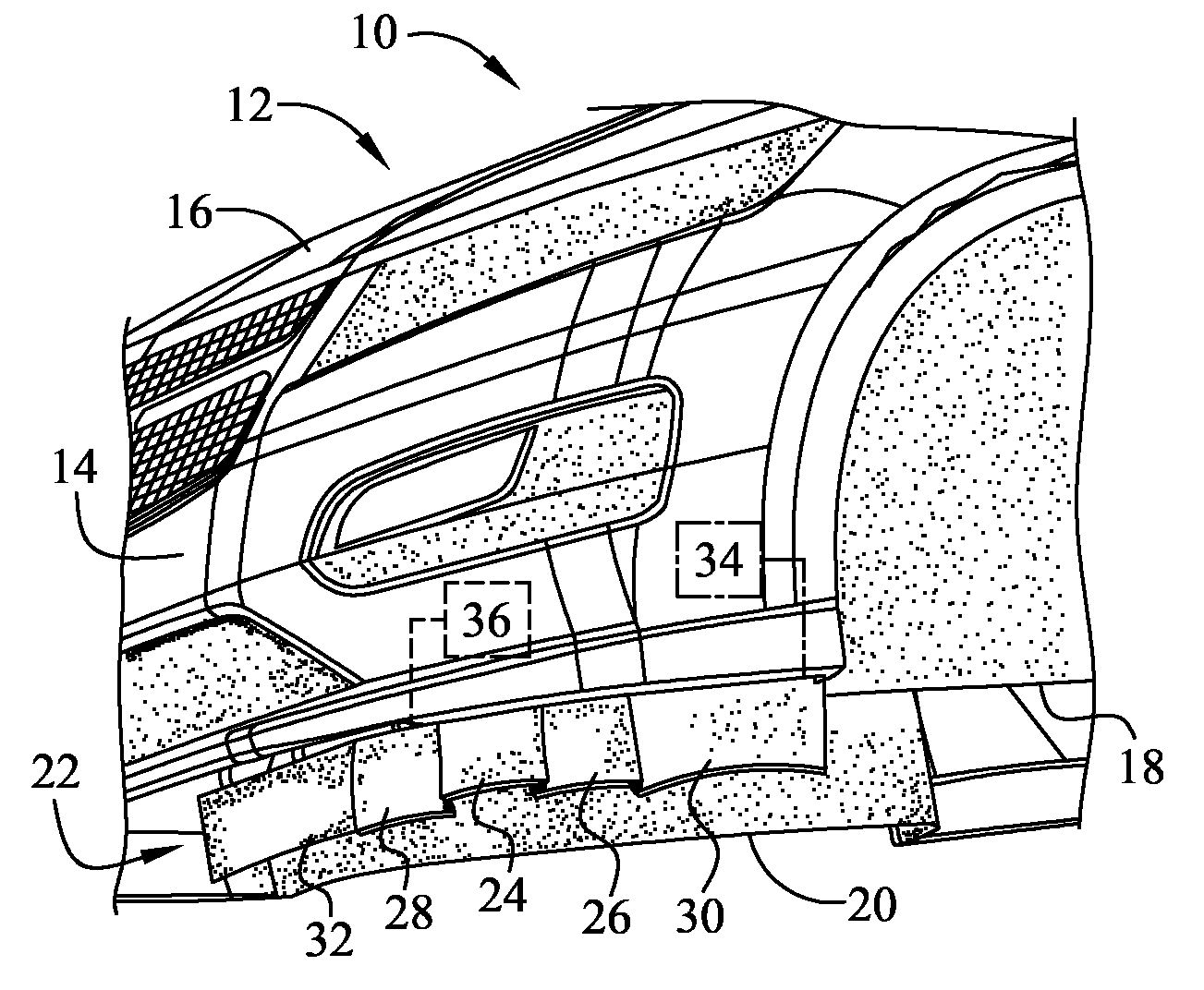
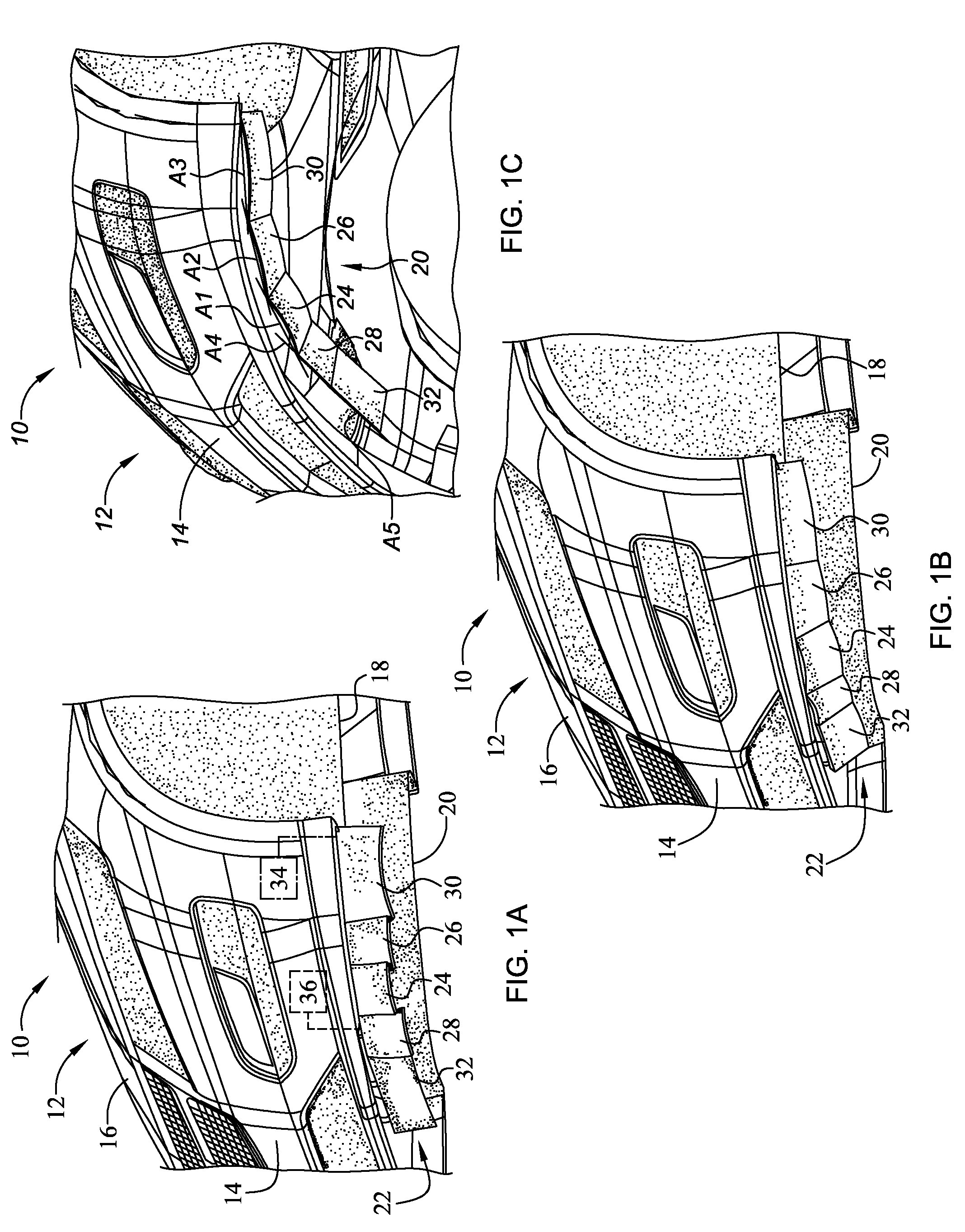
[0005]Presented herein is a segmented, retractable air dam assembly with plan view curvature for improving the aerodynamic characteristics of a motor vehicle. The air dam of the present invention can be positioned as low as needed for optimal aerodynamic performance, and stowed during operating conditions when optimal positioning might violate ramp angle and curb criteria. In addition, the air dam assembly is adapted to fold back or yield when hit by a parking curb, ramp, road incline, or other obstruction. The air dam design presented herein increases fuel economy (or vehicle range), eliminates inadvertent damage or breakage, improves cooling airflow, and eliminates the additional packaging space required for prior art retractable air dams.
[0011]In accordance with another embodiment of the present invention, an air dam assembly is provided for improving the aerodynamic characteristics of a motor vehicle. The air dam assembly includes a center panel member configured to suspend transversely from underneath the front vehicle structure. The center panel member is adapted to selectively pivot between a deployed position, in which the center panel member is in a non-horizontal orientation, and a stowed position, in which the center panel member is in a generally horizontal orientation. The air dam assembly also includes one or more side panel members that are configured to suspend from underneath the front vehicle structure in curvilinear relation to the center panel member. The side panels also pivot between a deployed position, in which each side panel member is in a non-horizontal orientation, and a stowed position, in which each side panel member is in a generally horizontal orientation. The center and side panel members sufficiently overlap such that pivoting the center panel member from the deployed position to the stowed position thereby pivots the side panel members to the stowed position, folded up against the underbody of the vehicle. Moreover, the center and side panel members sufficiently overlap such that pivoting one of the side panel members from the stowed position to the deployed position thereby pivots the center panel member to the deployed position, extending downward into proximity with the road surface.

Problems solved by technology

An air dam that is fixedly suspended from underneath the front-end structure of the vehicle may be damaged upon impact with a curb, driveway incline, or other roadway obstruction.
Such curved configurations inherently stiffen the air dam, which in turn limits the extent to which the air dam can yield when striking a curb or other obstruction.

Method used


Image

  • Retractable curved air dam
  • Retractable curved air dam

Examples


Embodiment Construction

[0020]Referring to the drawings, wherein like reference numbers refer to like components throughout the several views, FIGS. 1A-1C are perspective view illustrations of the underside front-end structure of an exemplary motor vehicle, generally indicated at 10, with which the present invention may be incorporated and practiced. It should be readily understood that the vehicle 10 shown herein is merely a representative application by which the present invention may be utilized. As such, the present invention is by no means limited to the vehicle configuration shown in the drawings. For example, although the vehicle 10 is depicted in FIGS. 1A-1C as a standard passenger car, the present invention can be incorporated into any motorized vehicle, such as, but not limited to, sport utility vehicles, light trucks, heavy duty vehicles, minivans, buses, tractor-trailers, etc. Finally, the drawings presented herein have been greatly simplified and are not to scale, and are thus provided purely ...


PUM


Abstract

A retractable curved air dam assembly is provided for improving the aerodynamic characteristics of a motor vehicle. The air dam assembly is segmented to include a plurality of panel members each adapted to pivotably attach to the underside of the front-end vehicle structure. The panel members are configured to selectively transition between a deployed position, in which the panel members are preferably in a generally vertical orientation, and a stowed position, in which the panel members are in a generally horizontal orientation. The panel members are shingled (i.e., partially overlapped) such that pivoting a center panel from the deployed position to the stowed position thereby pivots the side panels to the stowed position, and such that pivoting a side panel from the stowed position to the deployed position thereby pivots the center panels to the deployed position.

Description

TECHNICAL FIELD[0001]The present invention relates generally to devices for improving vehicle aerodynamics, and more specifically to retractable air dams for motor vehicles.BACKGROUND OF THE INVENTION[0002]Many conventional motor vehicles, such as the modern-day automobile, include an air dam that is engineered to improve the aerodynamic characteristics of the vehicle body. A traditional air dam, which is sometimes referred to as an “air deflector”, is mounted on the underside of the front-end structure of the vehicle body, extending downward into proximity with the roadway. Air dams improve the handling and control of the motor vehicle, increase fuel economy, and also improve the routing of air flow for cooling / heat exchange in the vehicle powertrain and air conditioning systems by managing the flow of turbulent air under and around the vehicle chassis and affecting internal airflows.[0003]An air dam that is fixedly suspended from underneath the front-end structure of the vehicle m...

Claims


Application Information

Patent Timeline
Patent Type & Authority Patents(United States)
IPC IPC(8): B60J9/04
CPCB62D35/005Y02T10/82
Inventor TORTOSA-BOONACKER, NINA
Owner GM GLOBAL TECH OPERATIONS LLC
Learn More