Automatically tuned tail filter

a tail filter and automatic tuning technology, applied in the direction of oscillating generators, multiple resonant circuits tuned to different frequencies, pulse automatic control, etc., can solve the problems of unnecessarily high phase noise, unnecessary noise generation of current sources, and poor switching performance, and achieve low current consumption , good switching performan

Inactive Publication Date: 2010-03-30
HIGHBRIDGE PRINCIPAL STRATEGIES LLC AS COLLATERAL AGENT
View PDF4 Cites 13 Cited by
  • Summary
  • Abstract
  • Description
  • Claims
  • Application Information

AI Technical Summary

Benefits of technology

[0006]What is needed is therefore an oscillating circuit arrangement as initially referred to which has a low phase noise. Most particularly an oscillating circuit arrangement is needed in which the resonator is loaded as little as possible by applied current biasing. Particularly an oscillating circuit arrangement is needed which also has a good switching performance, i.e. a high switching speed. Further yet an arrangement is needed which is robust and which has a low current consumption. Particularly an arrangement is needed which has a good performance in a broad frequency band and which is not sensitive to process variations, has a stable current bias, i.e. not sensitive to variations in gate / base bias, etc. Particularly an arrangement is needed which is capable to have a high performance in a broad frequency band also at low offset frequencies, which furthermore can be made as a small size device. Still further an arrangement is needed which is cheap and easy to fabricate and which has an extremely low phase noise.
[0007]A method for minimizing the phase noise of an oscillating circuit arrangement as initially referred to is also needed through which one or more above mentioned objects can be achieved.
[0008]Therefore an oscillating circuit arrangement as initially referred to is provided which comprises a tunable filter arrangement connected to the voltage controlled oscillator (VCO) arrangement. Said filter arrangement resonates at a second resonance frequency ωf, where the second resonance frequency is a multiple n,n=1 or 2 of said first resonance frequency, n being equal to the minimum number of functional switch transistors forming the VCO of the oscillating circuit arrangement required for the VCO to oscillate at said first (operating) frequency. The filter arrangement is tunable such that the phase noise of the resonating arrangement is minimized. Said filter arrangement particularly comprises an equivalent current source which comprises an inductor connected in parallel with a capacitor, said capacitor being adapted to be tunable such that the phase noise of the resonating arrangement is minimized.
[0014]Most particularly the VCO comprises an n-MOS complementary VCO and the tunable filter arrangement may be provided at the source node of the n-MOS transistors, at the source node of the p-MOS transistors or tunable filter arrangements may be provided at the source node of both the p-MOS transistor and the n-MOS transistor simultaneously, which however does not further increase performance.

Problems solved by technology

Such a configuration suffers mainly from three drawbacks.
First, the current source generates noise which is converted to oscillator phase noise.
Second, the current source requires a certain DC voltage drop across it in order to work properly.
Third, the limited impedance of the current source at RF frequency loads the resonator which also has a result that the phase noise will be unnecessarily high.
In addition thereto the limited impedance has a tendency to increase current consumption.
Further such a configuration will not be capable of suppressing common mode signals and disturbances and it will therefore be quite sensitive to noise.
Moreover the current consumption is increased.
However, such configurations will still suffer from drawbacks, first of all in that the current bias is very sensitive to variations in gate / base bias and thus temperature and process variations, which is similar to the configuration of FIG. 1B.
Further, it only gives an optimized performance in a very narrow frequency band and performs poorly over frequency tuning and it is also sensitive to process variations.
Such problems may be severe, particularly at low offset frequencies.

Method used


Image

  • Automatically tuned tail filter
  • Automatically tuned tail filter
  • Automatically tuned tail filter

Examples


Embodiment Construction

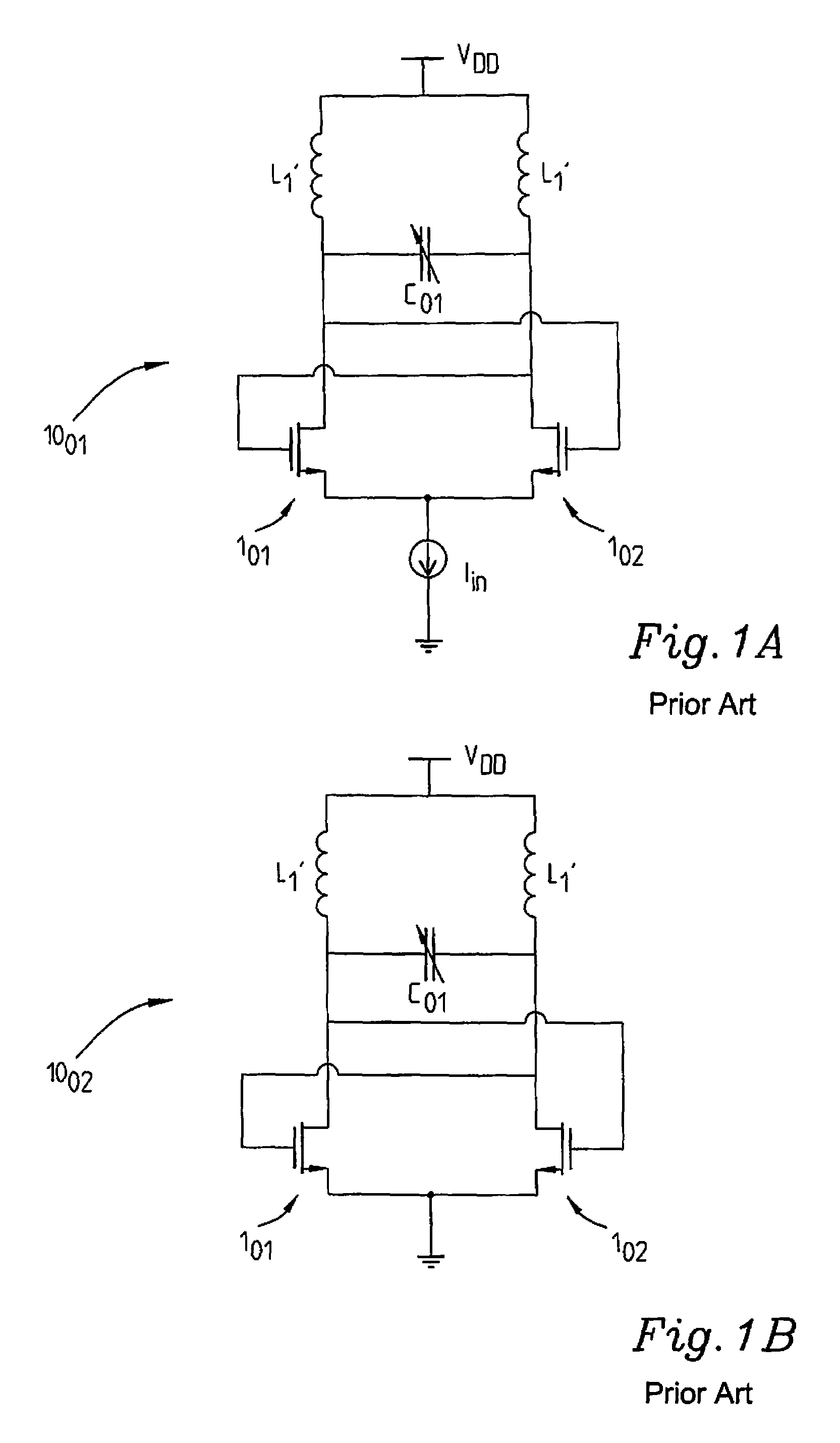
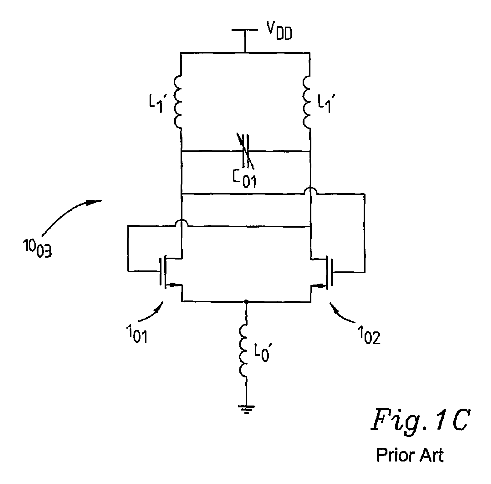
[0037]The state of the art FIGS. 1A-1C and the disadvantages associated therewith have been discussed earlier in the state of the art section since they constitute standard configurations of cross-coupled differential pair VCOs 1001, 1002, 1003 supplied with the voltage VDD and comprising a first and a second switch transistor 101, 102 and a varactor C01. The varactor C01 may, for example, be implemented as a MOS capacitor or as a p-n junction etc. Hence, as discussed in the state of the art section, the current source Iin is used to set the current bias in the implementation of FIG. 1A whereas FIG. 1B merely shows a grounded variation and FIG. 1C shows an arrangement in which the current source has been replaced by an inductor L01.

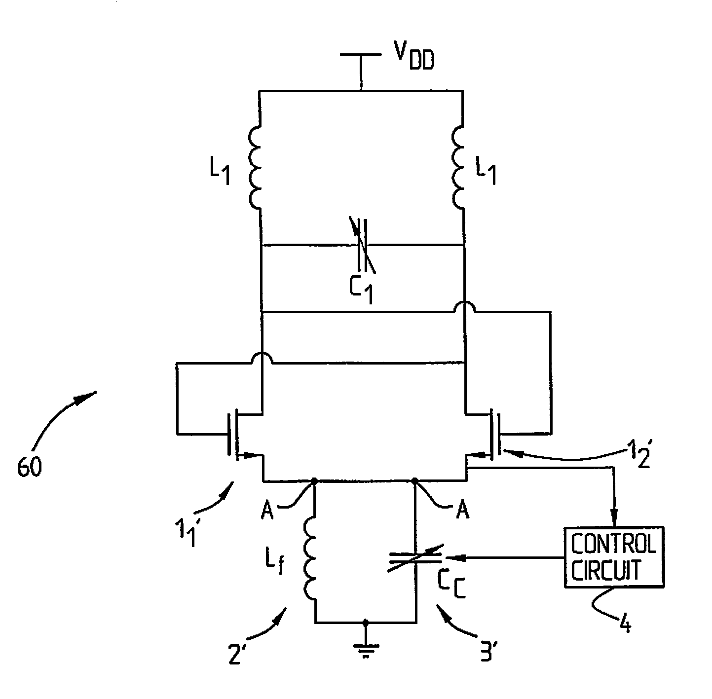
[0038]FIG. 2 shows a first embodiment of the present invention. The oscillating circuit arrangement 10 here comprises a cross-coupled differential pair VCO structure, in a conventional manner. The first (functional) switch transistor 11 and the second (fu...


PUM


Abstract

The present invention relates to an oscillating circuit arrangement having a resonating arrangement with a first resonance frequency (coo) comprising a voltage controlled oscillator arrangement. It further comprises a tunable filter arrangement connected to the source node of said voltage controlled oscillator (VCO) arrangement. Said filter arrangement particularly comprises an equivalent current source resonating at a second resonance frequency cθf, the second resonance frequency being a multiple n, n=1 or 2 of said first resonance frequency (α>o), n being equal to the minimum number of switch transistors required for oscillation of said VCO arrangement. The filter arrangement particularly comprises an inductor connected in parallel with a capacitor, said capacitor being adapted to be tunable such that the phase noise of the resonating arrangement can be minimized through tuning of the filter arrangement.

Description

FIELD OF THE INVENTION[0001]The present invention relates to an oscillating circuit arrangement with a resonating arrangement resonating at a first resonance frequency and comprising a voltage controlled oscillator arrangement. The invention also relates to a method for minimizing the phase noise of an oscillating circuit arrangement including a resonating arrangement resonating at a first resonance frequency and comprising a voltage controlled oscillator arrangement.STATE OF THE ART[0002]Many different oscillating circuit arrangements comprising one or more Voltage Controlled Oscillators, in the following denoted VCO, are known. It is mostly of high importance to keep the phase noise as low as possible. A commonly used VCO topology comprises a common source / common emitter cross-coupled differential pair which is attractive due to its comparatively low phase noise, robust operation and since it can be made very small. In the state of the art FIG. 1A a cross-coupled differential pair...

Claims


Application Information

Patent Timeline
Patent Type & Authority Patents(United States)
IPC IPC(8): H03B5/12H03L5/00
CPCH03J3/32H03B5/1228H03B5/1215H03B5/1278H03B5/124H03B5/1284
Inventor JACOBSSON, HARALDASPEMYR, LARS
Owner HIGHBRIDGE PRINCIPAL STRATEGIES LLC AS COLLATERAL AGENT
Why Eureka
Try Eureka