Suspension structure with improved shock absorber arrangement, and vehicle incorporating same

a suspension structure and shock absorber technology, applied in the direction of bicycles, transportation and packaging, motorcycles, etc., can solve the problem of limited layout and achieve the effect of increasing the support rigidity of the lower end portion of the damper

Inactive Publication Date: 2010-04-06
HONDA MOTOR CO LTD
View PDF16 Cites 34 Cited by
  • Summary
  • Abstract
  • Description
  • Claims
  • Application Information

AI Technical Summary

Benefits of technology

[0010]According to the first aspect of the invention, since the connecting portion, or lower end portion, of the damper is cantilevered, mounting flexibility above the suspension arm is increased and hence, the arrangement permitting an increased shock absorber stroke is possible.
[0022]According to the seventh aspect of the invention, since a cantilever load of the connecting portion of the damper can be supported on the whole supporting portion, the supporting rigidity of the lower end portion of the damper can be further increased.

Problems solved by technology

In the related art shown above, since the lower end portion of the damper is located inside the suspension arms in the longitudinal direction, the layout of the lower end portion is apt to be limited, due to the relation between the knuckle and the power transmission shaft.

Method used


Image

  • Suspension structure with improved shock absorber arrangement, and vehicle incorporating same
  • Suspension structure with improved shock absorber arrangement, and vehicle incorporating same
  • Suspension structure with improved shock absorber arrangement, and vehicle incorporating same

Examples


first embodiment

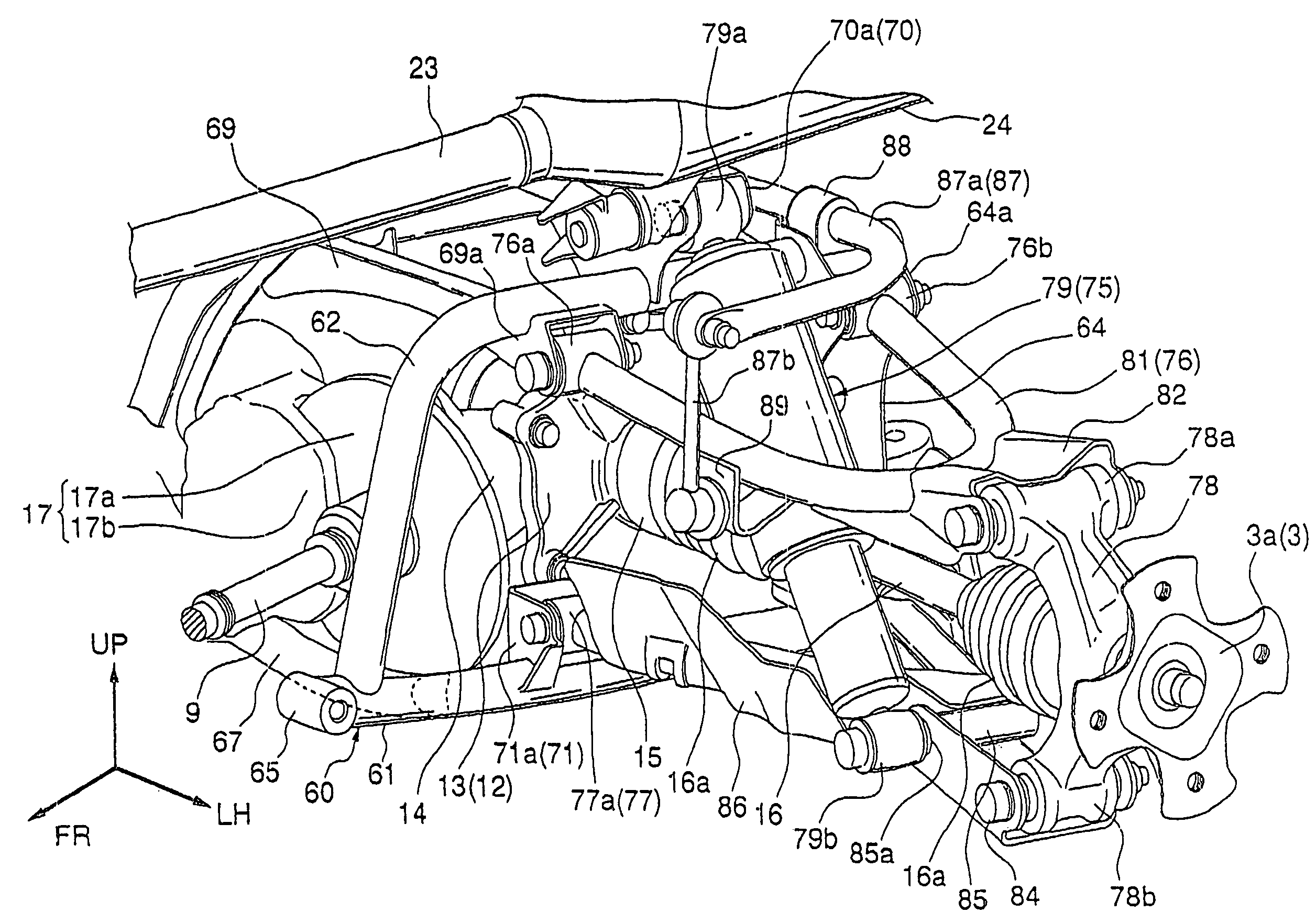
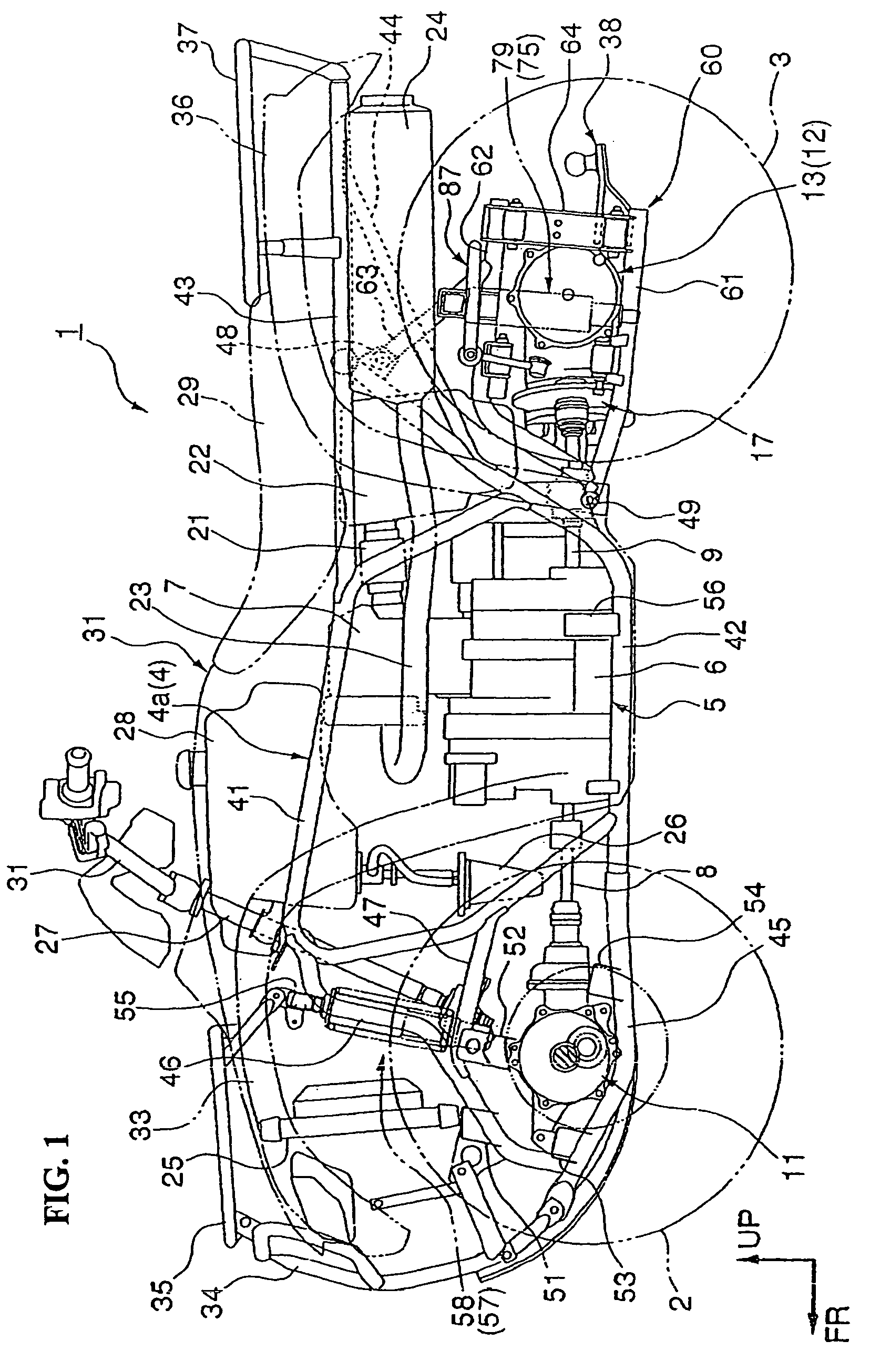
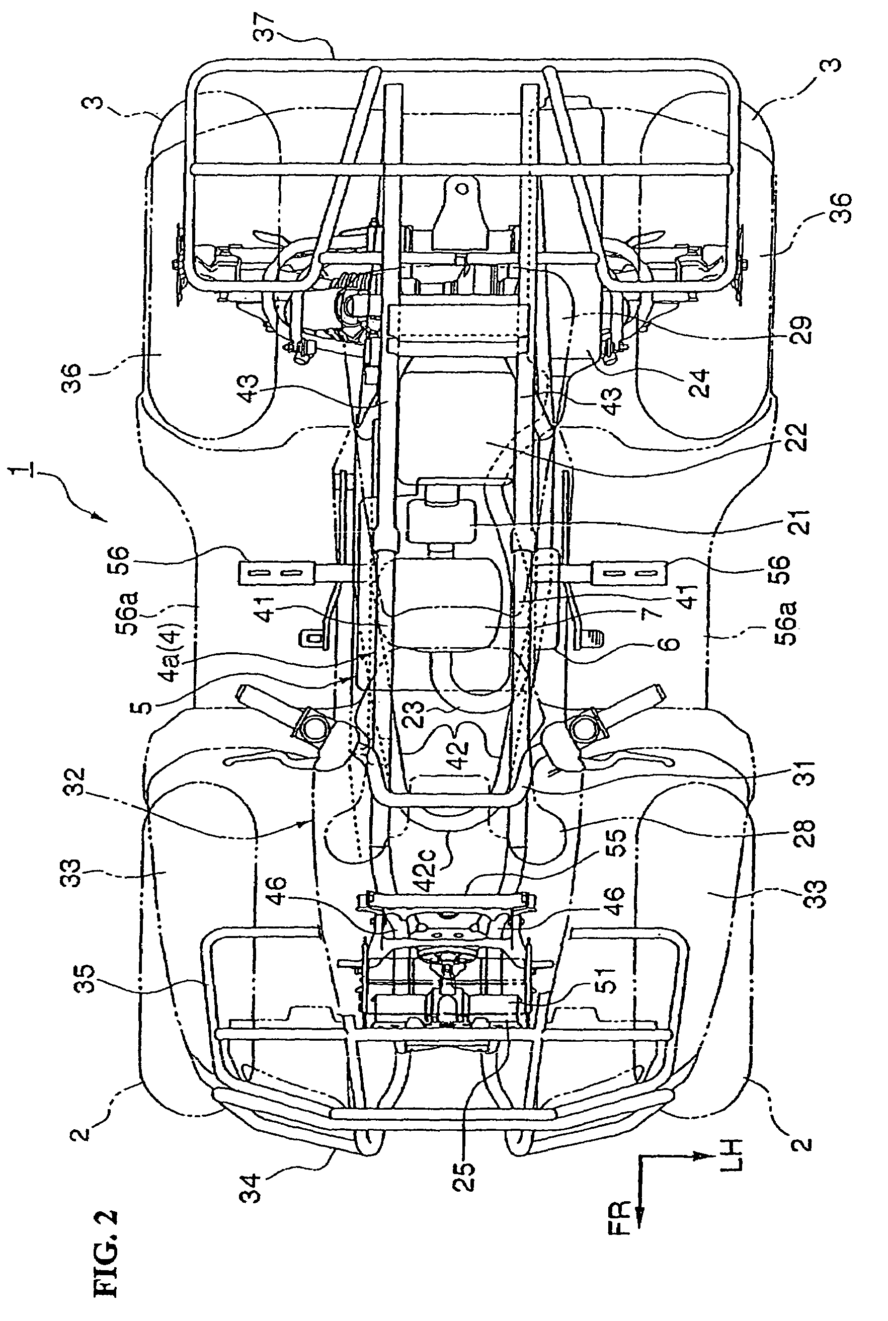
[0036]Referring now to FIGS. 1-2, the invention will now be described, with respect to a saddle-type four-wheel all-terrain vehicle 1 (commonly referred to as an ATV), designed for operation on rough terrain. The vehicle 1 includes left and right front wheels 2 and rear wheels 3. The wheels 2, 3 are provided with low-pressure balloon tires, of relatively large diameter, located at the front and rear of the vehicle body, respectively. The vehicle body is configured to be compact and light in weight, and has a large minimum ground clearance for enhancing traveling performance mainly on the rough terrain. A vehicle body frame 4 of this saddle-type four-wheel all-terrain vehicle 1 includes a separate sub-frame 60 (FIGS. 1, 4) integrally connected to the rear portion of a frame body 4a.

[0037]Both of the front wheels 2 are suspended by way of front suspensions 57. The front suspensions 57 are of an independent suspending type (double wishbone type). Both of the rear wheels 3 are suspende...

second embodiment

[0100]Next, the invention is explained in conjunction with FIG. 10.

[0101]In this embodiment, a point which substantially makes this embodiment differ from the above-mentioned first embodiment lies in that a lower arm 177 is adopted in place of the lower arm 77. Here, parts identical with the parts shown in the first embodiment are given the same symbols and their redundant explanation is omitted.

[0102]The lower arm 177 includes a lower damper supporting pipe 185 in place of the lower damper supporting pipe 85. The lower damper supporting pipe 185 has a diameter of an inner periphery of a front portion thereof narrowed and forms a threaded hole 185a in the narrow-diameter portion. In the threaded hole 185a, a proximal-end-side male threaded portion 190a of a stud shaft 190 which constitutes a connecting shaft of the lower end connecting boss 79b of the rear shock absorber 79 is threadably engaged and fixed. Accordingly, on the front-end side of the lower damper supporting pipe 185, a...


PUM


Abstract

A suspension structure is configured to ensure a large stroke of a shock absorber in a suspension device without moving an upper end supporting position of a damper upward relative to a conventional mounting position. The suspension structure includes a rear suspension for suspending left and right rear wheels. The rear suspension includes left and right lower arms for supporting the left and right rear wheels by way of knuckles, and left and right rear shock absorbers interposed between the respective lower arms and a sub-frame of a vehicle body frame. A lower end connecting portion of the rear shock absorber is cantilevered to a front side of the lower arm.

Description

CROSS-REFERENCE TO RELATED APPLICATIONS[0001]The present invention claims priority under 35 USC 119 based on Japanese patent application Nos. 2006-022882, filed on Jan. 31, 2006 and 2006-308832, filed on Nov. 15, 2006. The subject matter of these priority documents is incorporated by reference herein.BACKGROUND OF THE INVENTION[0002]1. Field of the Invention[0003]The present invention relates to a suspension structure for a vehicle provided with wheels on the left and right sides of a vehicle body, such as an all-terrain vehicle (ATV).[0004]2. Description of the Background Art[0005]In the related art, in the suspension of an ATV, there is a known structure in which left and right rear wheels are respectively supported by suspension arms by way of knuckles, and dampers are interposed between the suspension arms and a rear portion of a vehicle body frame. Such a suspension structure is disclosed, for example, in JP-A-2001-328410. A rear terminal gear case is arranged in the rear porti...

Claims


Application Information

Patent Timeline
Patent Type & Authority Patents(United States)
IPC IPC(8): B60G3/20B60G7/00B60G13/06B62K5/00B62K5/01
CPCB60G3/20B60G11/15B60G21/055B62K5/01B60G2200/144B60G2206/12B60G2300/12B60G2300/13B60G2202/12Y10S180/908
Inventor TSURUTA, YUICHIROSHICHINOHE, TAKASHIYAMAGUCHI, MASAHIRO
Owner HONDA MOTOR CO LTD
Why Eureka
Try Eureka