Driver circuit

a technology of driving circuit and drive pin, which is applied in the direction of logic circuit coupling/interface arrangement, pulse technique, baseband system details, etc., to achieve the effect of simple implementation

Inactive Publication Date: 2010-04-06
GLOBALFOUNDRIES INC
View PDF9 Cites 24 Cited by
  • Summary
  • Abstract
  • Description
  • Claims
  • Application Information

AI Technical Summary

Benefits of technology

[0006]It is advantageous that the output impedance does not depend on the operation mode of the main units and does not depend on the sub units being switched to either the first or the second reference potential. The drive strength depends on the ratio of the number of main units operated in data mode to the number of main units operated in termination mode. Main units operated in data mode increase the drive strength of the driver circuit and main units operated in termination mode reduce the drive strength of the driver circuit. The advantage is that the drive strength can be adjusted easily by setting individual main units to either data mode or termination mode. By this, voltage margining can be performed easily for testing purposes. Sub units of each main unit set to data mode can be controlled easily to further influence the drive strength depending on the data signal to transmit. A further advantage is that the driver circuit has a simple architecture and is therefore easy to implement and control. The at least two main units may be equal main units.
[0019]The advantage is that the driver circuit is simple to implement. The disabled mode of the respective main unit can be provided easily by switching both switching elements off in all sub units of the respective main unit. In the enabled mode of the respective main unit, one of the switching elements in each sub unit of the respective main unit is switched on, the other switching element is switched off.

Problems solved by technology

It is a challenge to provide a driver circuit with advantageous voltage margining functionality.
It is a further challenge to provide a driver circuit with advantageous termination impedance matching functionality.

Method used


Image

  • Driver circuit
  • Driver circuit
  • Driver circuit

Examples


Embodiment Construction

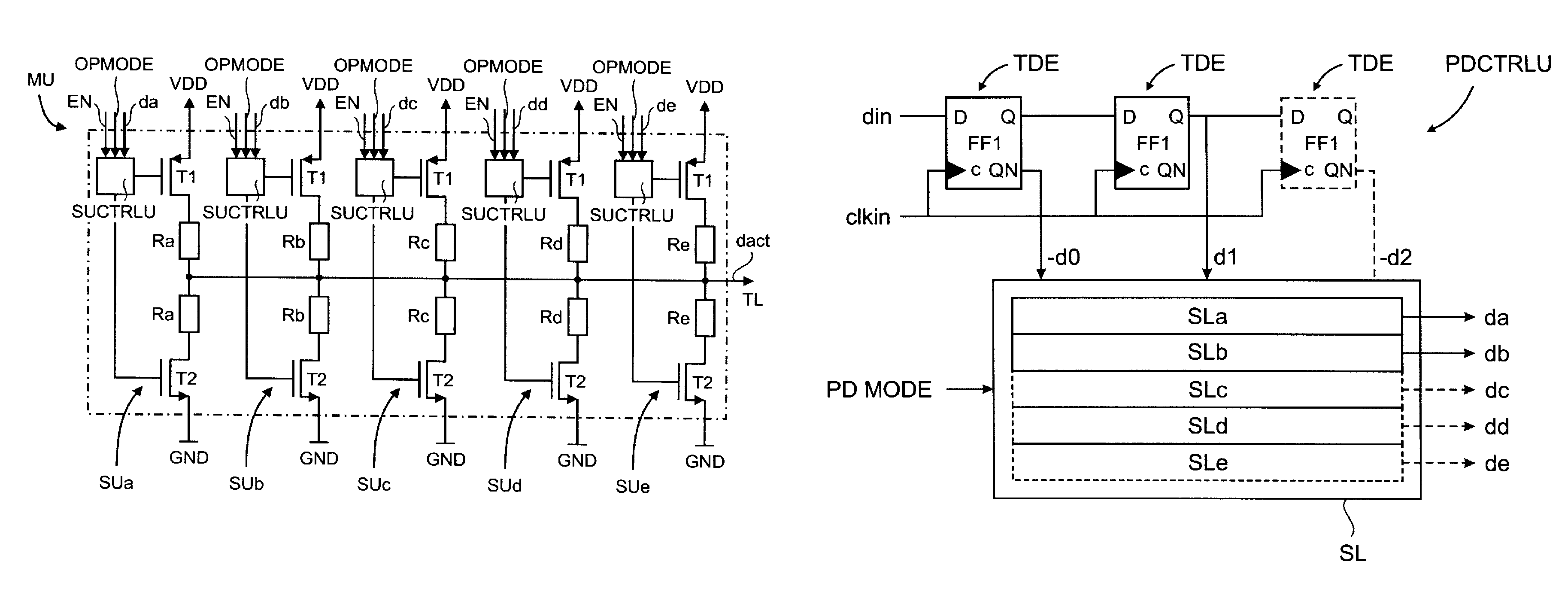
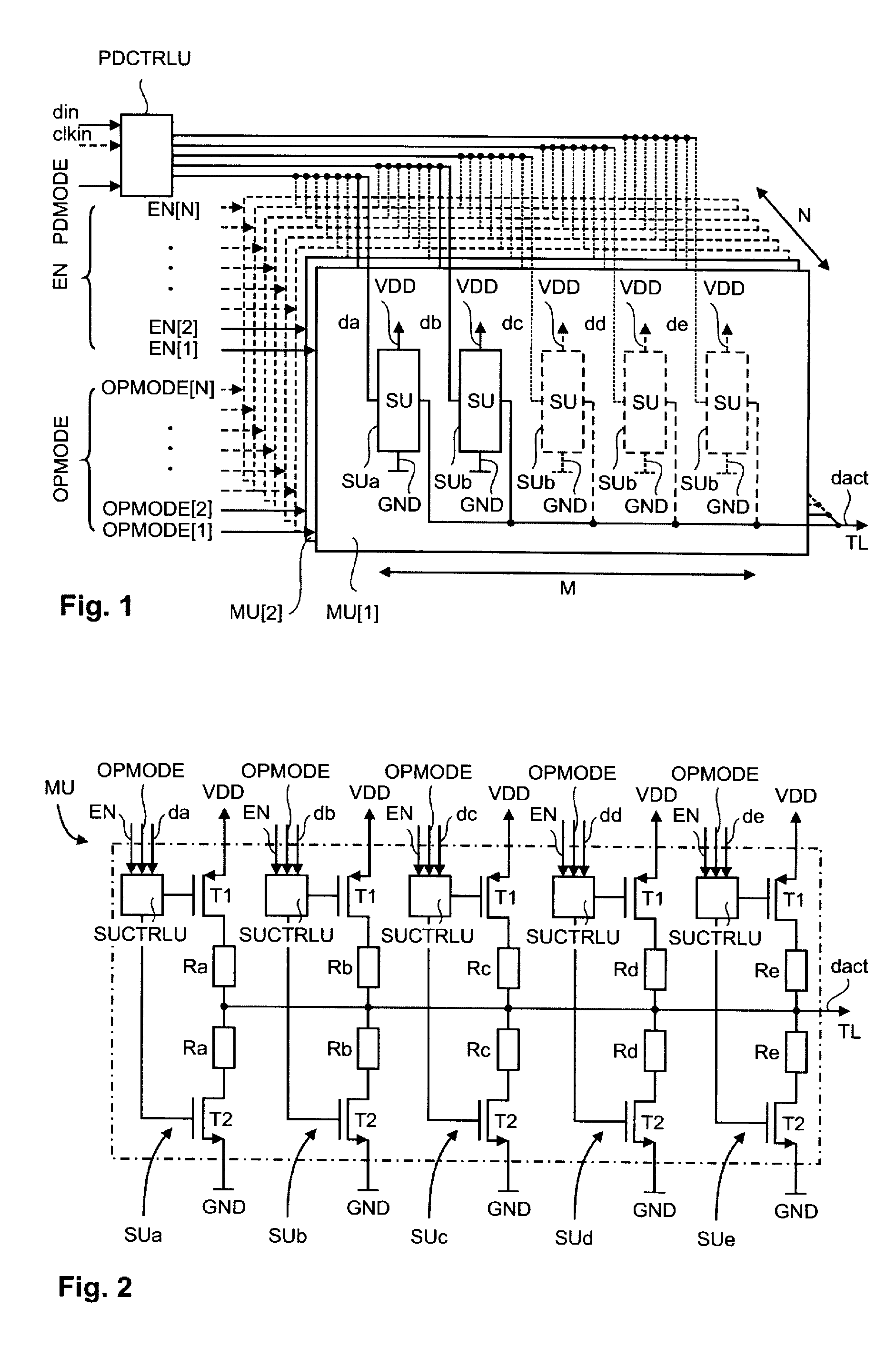
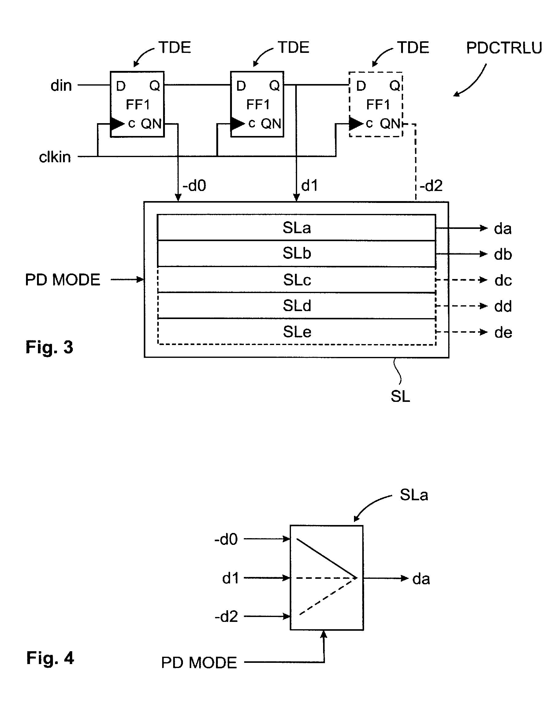
[0028]Line drivers are an important building block in data input / output transmission systems. They encode data symbols into a traveling wave signal to be transmitted over a transmission channel, e.g. a transmission line TL. The vast majority of high-speed transmission systems is limited by a non-ideal transmission channel, in particular with respect to frequency dependent channel loss and channel line impedance discontinuities. In order to allow for a reliable data detection at a receiver, special measures are used to compensate for these adverse effects. These measures comprise channel equalization and termination impedance control. There is further a desire for monitoring of the transmission reliability. For this, the signal strength is gradually reduced in order to find a detection limit and an available margin while maintaining termination impedance and channel equalization constant. This procedure is called “voltage margining”.

[0029]In the following is described a driver circui...


PUM


Abstract

A driver circuit is provided comprising at least two equal main units (MU) each comprising at least two sub units (SU) coupled to a data output (dout). Each sub unit (SU) is adapted to represent a respective predetermined impedance. Each main unit (MU) is adapted to that, when in a data mode, each sub unit (SU) of the respective main unit (MU) is switchable to either a first or second reference potential depending on a data signal to transmit. Each main unit (MU) is further adapted to that, when in a termination mode, the sub units (SU) of the respective main unit (MU) are switched to either the first or second reference potential such that an output of the respective main unit (MU) is neutral with respect to the driving of the data output (dout) to the first or second reference potential.

Description

CROSS-REFERENCE TO RELATED APPLICATIONS[0001]This application claims priority under 35 U.S.C. § 119 to EP Application No. 07 / 108440 filed May 18, 2007, the entire content of which is specifically incorporated by reference herein.TECHNICAL FIELD[0002]The present invention relates to a driver circuit for driving a transmission line for transmitting data.BACKGROUND OF THE INVENTION[0003]U.S. Pat. No. 6,930,506 B2 discloses a terminating resistor driver for high speed data communication. The driver circuit has a plurality of parallel units each comprising two resistors and an upper and a lower switch. The resistors are each connected to a transmission line with one end and connected to the upper or the lower switch, respectively, with the other end. The upper switch is further connected to an upper reference potential and the lower switch is further connected to a lower reference potential. A total impedance of all the resistors equals an impedance of the associated transmission line.[0...

Claims


Application Information

Patent Timeline
Patent Type & Authority Patents(United States)
IPC IPC(8): H03K17/16
CPCH03K17/164H04L25/0278H03K19/0005H04L25/028
Inventor CRANFORD, JR., HAYDEN CLAVIEMENOLFI, CHRISTIAN I.SCHMATZ, MARTIN LEOTOIFL, THOMAS H.
Owner GLOBALFOUNDRIES INC
Why Eureka
Try Eureka