
Method and apparatus for faster-than-real-time lossless compression and decompression of images

a lossless compression and image technology, applied in the field of data compression and decompression, can solve the problems of consuming a lot of time and computing resources, and achieving the effect of minimizing the demand on system resources, maximizing the compression ratio, and maximizing the compression power

Inactive Publication Date: 2010-04-06
WITTENSTEIN ANDREAS
View PDF7 Cites 42 Cited by
  • Summary
  • Abstract
  • Description
  • Claims
  • Application Information

AI Technical Summary

Benefits of technology

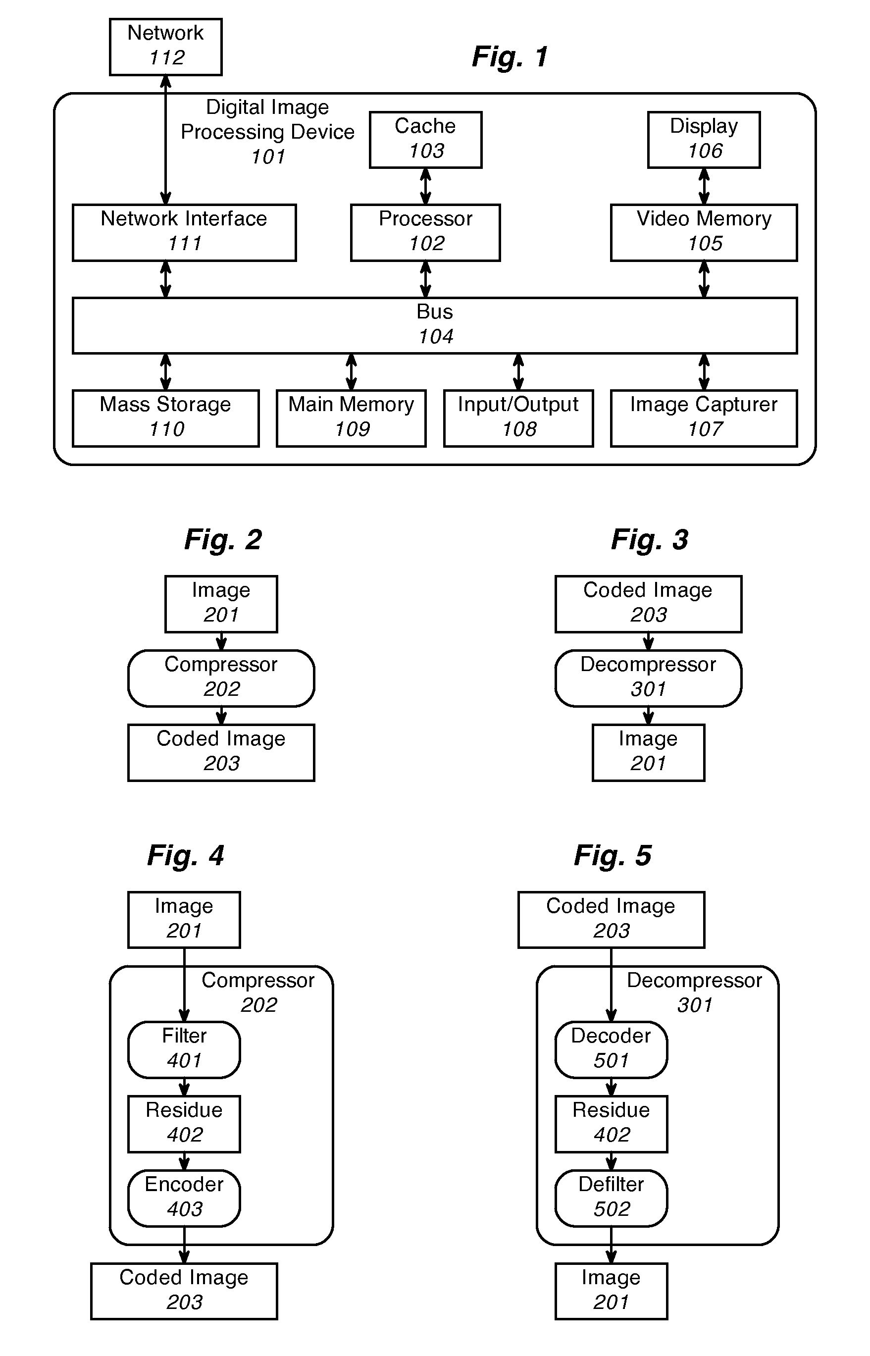
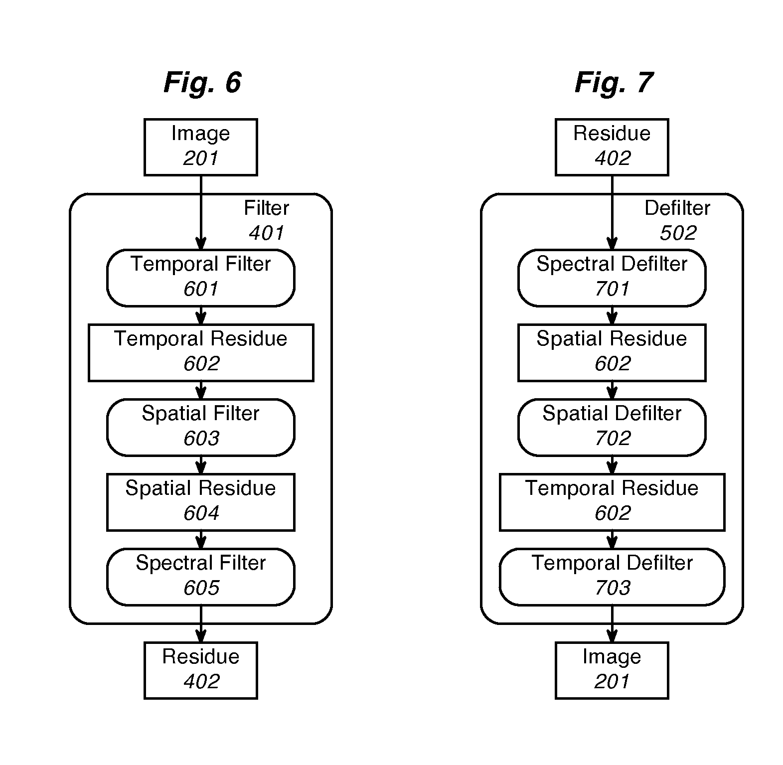
"The present invention provides a method and apparatus for compressing and decompressing image data quickly and without information loss. The method uses a symmetrical compression-decompression scheme that maximizes the compression ratio on current consumer-level computers in real-time. The compressor and decompressor are optimized to minimize the demand on system resources such as code space, data space, image cache space, memory bandwidth, bus bandwidth, processor precision, and processor complexity. The compressor steps through a process of condensing the image with a filter, optionally reducing the residue, and then encoding it into a stream of variable-bit-length codes. The decompressor decodes the bitstream into the identical residue, which is then defiled into the original image. The compression filter uses a quasilinear one-sided prediction-error filter, with temporal, spatial, and spectral stages to minimize computation and storage of intermediate values. The filter coefficients are chosen to be small integers, so low-level hardware or firmware can implement them. The filter support consists of adjacent causal samples of the image. The encoding and decoding processes use chunked decode tables for accelerated lookup, allowing for decoding several bits at once. The code lengths are preferably limited to 1 chunk longer than the samples for speed and compactness of code and tables. The context-specific code tables are generated based on the probability of occurrence of the code and the adjacent causal residue samples. The invention provides a faster and more efficient way to compress and decompress image data."

Problems solved by technology

Saturation arithmetic yields slightly higher compression power, but is generally more expensive to implement.

Method used


Image

  • Method and apparatus for faster-than-real-time lossless compression and decompression of images
  • Method and apparatus for faster-than-real-time lossless compression and decompression of images
  • Method and apparatus for faster-than-real-time lossless compression and decompression of images

Examples


implementation examples

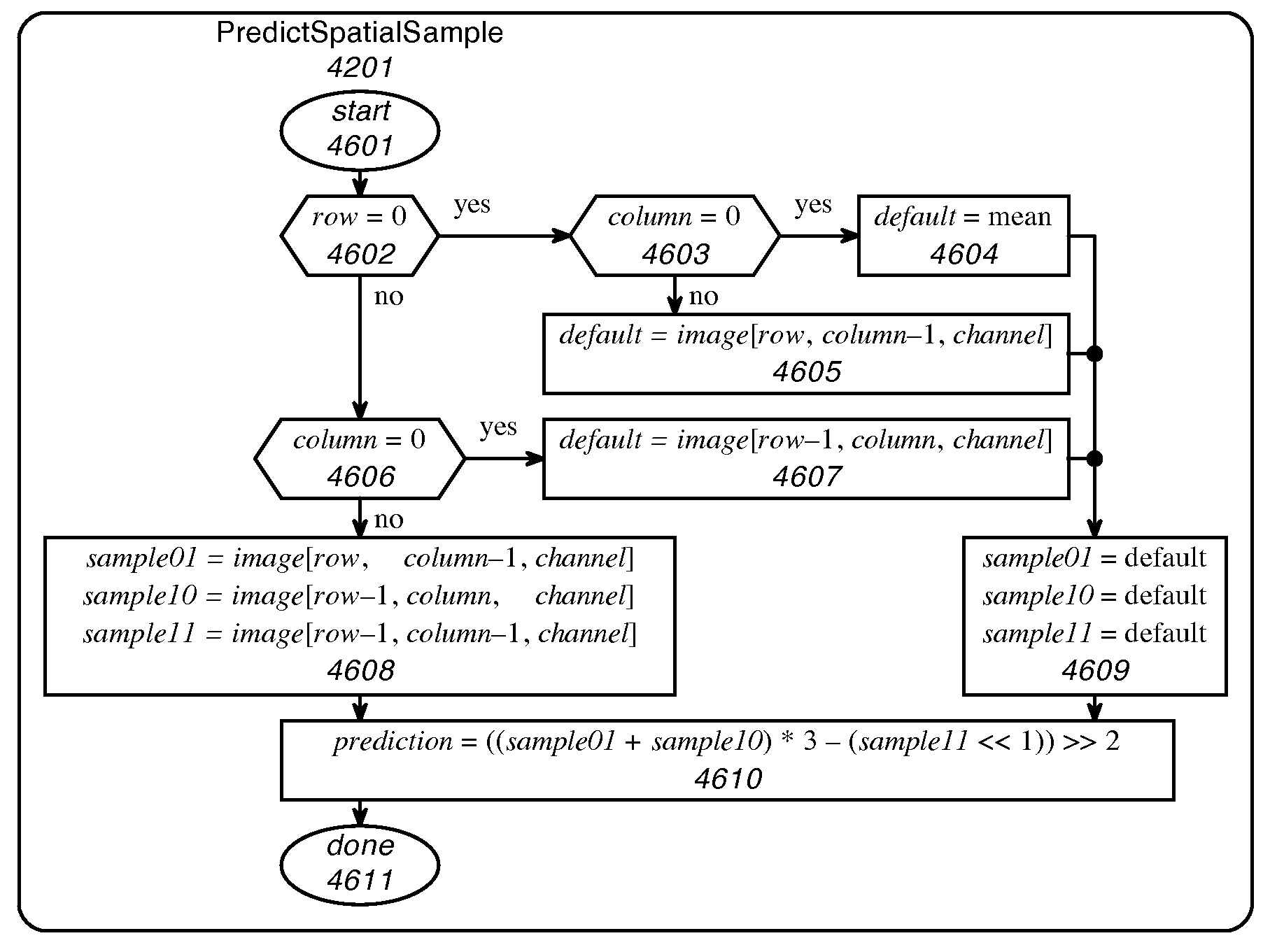
[0116]FIG. 38 and FIG. 39 show the process flow for a compact, simple fast-mode implementation of the image compressor and decompressor tailored for two-dimensional color images and designed to run on a sequential processor. For illustration purposes, the diagrams use C-like pseudocode. The CompressImage procedure in FIG. 38 executes a three-level nested loop, processing the sample in every channel in every column in every row, at the center of which the current sample is compressed by procedure CompressSample 3808. The DecompressImage procedure in FIG. 39 executes an identical three-level loop to decompress every sample in procedure 3908.

[0117]FIG. 40 reveals the CompressSample procedure 3808 to consist of three sequential subprocedures: FilterSpatialSample 4001, FilterSpectralSample 4002, and EncodeSample 4003. FIG. 41 reveals the DecompressSample procedure 3908 to consist of the opposite three subprocedures in the opposite order DecodeSample 4101, DefilterSpectralSample 4102, and...

table examples

Code Table Examples


PUM


Abstract

Image compression wherein a spatial prediction filter combines two adjacent samples and a corner sample in the proportion 3:3:−2, or wherein chunked decode tables are used to decode embedded prefix codes more than one bit at a time. A spectral prediction filter might be used in conjunction with the spatial prediction filter. Chunked decode tables might be used in combination with simple prediction filters.

Description

CROSS-REFERENCE TO RELATED INVENTION[0001]This invention claims priority to Provisional Patent Application Ser. No. 60 / 530,594, entitled “Method And Apparatus For Faster-Than-Real-Time Lossless Compression And Decompression Of Images”, filed on 8 Dec. 2003.BACKGROUND OF THE INVENTION[0002]1. Field of the Invention[0003]This invention relates to the field of data compression and decompression, in particular to compression and decompression of still and moving digital color images.[0004]2. Background Art[0005]Various compression schemes have been developed to reduce the transmission bandwidth and storage requirements for image and video data without information loss. Prior-art compression schemes include LZW and PNG, JPEG-DPCM, PhotoJazz, JPEG-LS, fractals, and wavelets. Understanding of this invention depends on a background in prior-art theory and practice relating to color compression, spatial image compression, and temporal moving-image compression.[0006]Data compression refers to...

Claims


Application Information

Patent Timeline
Patent Type & Authority Patents(United States)
IPC IPC(8): G06K9/36G06K9/46
CPCH04N19/80H04N19/59H04N19/90
Inventor WITTENSTEIN, ANDREAS
Owner WITTENSTEIN ANDREAS
Learn More