
Method for producing resin structure

a resin structure and resin technology, applied in the field of resin structure production, can solve the problems of difficult shape of resin layer, difficult contact between inner resin layer and outer shell resin layer, etc., and achieve the effect of easy shaping of hollow structur

Inactive Publication Date: 2010-04-13
TOYOTA JIDOSHA KK
View PDF6 Cites 8 Cited by
  • Summary
  • Abstract
  • Description
  • Claims
  • Application Information

AI Technical Summary

Benefits of technology

[0006]It is therefore an object of the present invention to provide a method for producing a resin structure which can easily shape a hollow structure even when it has a complicated inner form such as a honeycomb form, and can bring an inner resin layer and an outer shell resin layer into close contact with each other.
[0008]The method for producing a resin structure in accordance with the present invention arranges an outer shell resin matrix to become an outer shell resin member along a side wall of an inner preform, so as to make a preliminary structure, heats the preliminary structure while vacuuming the inside thereof, and then finally heats the preliminary structure while imparting an internal pressure thereto, so as to produce the resin structure. Therefore, unlike the case using a bag or the like, the inner preform arranged on the inside can be shaped easily even when it has a complicated form. Since vacuum suction is carried out in the process of heating the preliminary structure, the outer shell resin member matrix can be brought into close contact with the inner preform even when the latter has a complicated form.
[0011]When the completely cured resin tube is attached to the inner preform, and the internal pressure is imparted to the preliminary structure through the resin tube as such, the internal pressure can easily be imparted to the preliminary structure.
[0013]Even when the inner preform having a honeycomb form is used as such, the outer shell resin member matrix can reliably be brought into close contact with the inner preform. Here, linearly bonding prepregs located adjacent to each other in the stacking direction in a plurality of overlapping prepreg layers to each other at a predetermined interval and unfolding the plurality of prepregs can easily make the inner preform having a honeycomb form.
[0015]When the internal pressure is imparted to a plurality of spaces formed by the inner preform and outer shell resin member through a communication hole communicating the spaces with each other as such, the inner preform can be kept from being deformed by the internal pressure.
[0016]The method for producing a resin structure in accordance with the present invention can easily shape a hollow structure even when it has a complicated inner form such as a honeycomb form, and can bring an inner resin layer and an outer shell resin layer into close contact with each other.

Problems solved by technology

In the case where the inner resin layer has a complicated form such as a honeycomb form so that a side wall of the inner resin layer opposes the inner side face of the outer shell resin layer, however, the inner resin layer cannot be pressed against the outer shell resin layer even when the bag is used.
This has been problematic in that the inner resin layer is hard to shape, while it is difficult for the inner resin layer and the outer shell resin layer to come into close contact with each other.

Method used


Image

  • Method for producing resin structure
  • Method for producing resin structure
  • Method for producing resin structure

Examples


Embodiment Construction

[0032]In the following, embodiments of the present invention will be explained with reference to the accompanying drawings. In the explanation of the drawings, the same constituents will be referred to with the same numerals or letters while omitting their overlapping descriptions. For convenience of illustration, ratios of sizes in the drawings do not always coincide with those explained.

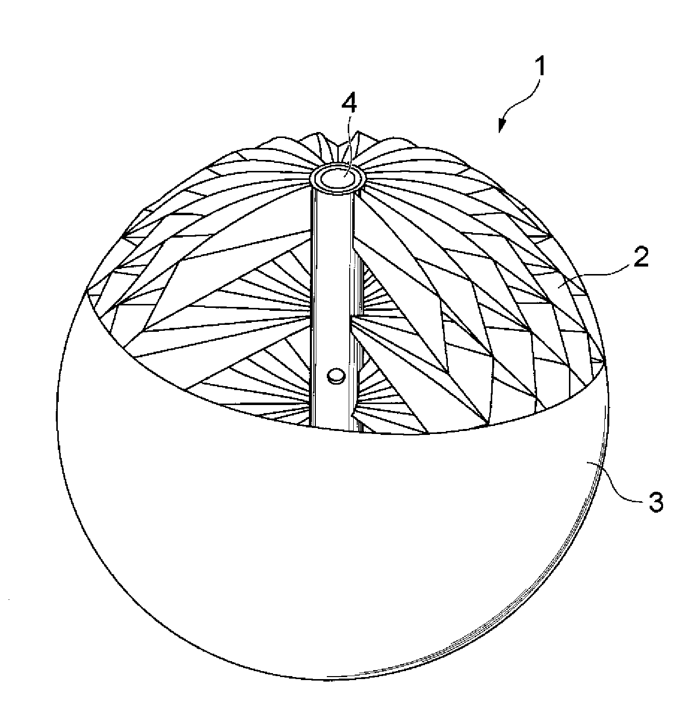
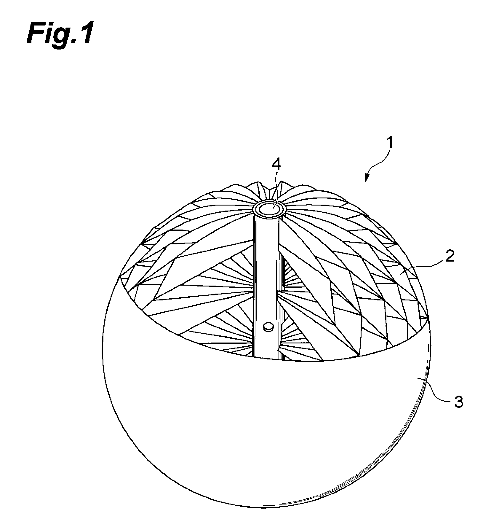
[0033]FIG. 1 is a partly broken perspective view of a resin structure produced by the method in accordance with an embodiment of the present invention. The resin structure 1 in accordance with this embodiment shown in FIG. 1 is a hollow structure made of FRP (Fiber Reinforced Plastics). As shown in FIG. 1, the resin structure 1 includes an inner structure 2 to become an inner preform, while an outer shell structure 3 is provided about the inner structure 2. The inner structure 2 is shaped like a sphere as a whole, while partly having a honeycomb form. A center tube 4, which is a resin tube, is plac...


PUM

PropertyMeasurementUnit
widthaaaaaaaaaa
temperatureaaaaaaaaaa

Abstract

A macrocell structure 20 having a honeycomb form is preheated to cure to a cure depth falling within a range where a flexibility of prepregs in the macrocell structure remains. Subsequently, prepregs 31, 32 are arranged along a side wall of the preheated macrocell structure 20, so as to make a preliminary structure 40. Then, the preliminary structure 40 is heated while the inside of the prepregs 31, 32 in the preliminary structure 40 is vacuumed. Thereafter, the preliminary structure 40 is heated while imparting an internal pressure thereto within a mold 5, so as to be cured, whereby a resin structure 1 is produced.

Description

BACKGROUND OF THE INVENTION[0001]1. Field of the Invention[0002]The present invention relates to a method for producing a resin structure.[0003]2. Related Background Art[0004]As a resin structure, one having a hollow part formed therewithin has conventionally been known. An example of methods for producing this kind of resin structure is one disclosed in Patent Document 1. This method comprises overlaying a prepreg on an inner face of a mold, placing a bag adapted to inflate when filled with pressurized air on the inside of thus obtained prepreg laminate, and heating to cure the prepreg laminate while pressing it against the inner face of the mold by inflating the bag (Patent Document 1: Japanese Patent Publication No. 3690744).SUMMARY OF THE INVENTION[0005]Also known as this kind of resin structure is one using the resin structure disclosed in the above-mentioned Patent Document 1 as an outer shell resin layer, while forming an inner resin layer in a hollow part formed on the insid...

Claims


Application Information

Patent Timeline
Patent Type & Authority Patents(United States)
IPC IPC(8): B29C47/76B29C45/14B29C47/00B29C70/44B32B3/00B29C48/76
CPCB29D22/00B29D24/001B29D99/0089B29D24/005Y10T156/1003Y10S264/50
Inventor OYAMA, HIROYUKI
Owner TOYOTA JIDOSHA KK
Learn More