Dissimilar material weld joint formed by joining iron type material and aluminum type material, and weld joining method

a technology of iron type material and aluminum type material, which is applied in the direction of manufacturing tools, welding apparatus, transportation and packaging, etc., can solve the problems of brittle intermetallic compounds inside the bead, the fatigue strength of the weld joint is reduced, and the bead surface cracks, etc., to prevent the cracking of the bead surface, high joint strength, and high joint strength

Inactive Publication Date: 2010-04-20
KOBE STEEL LTD
View PDF10 Cites 10 Cited by
  • Summary
  • Abstract
  • Description
  • Claims
  • Application Information

AI Technical Summary

Benefits of technology

[0028]In this light, the object of the present invention is: to further improve the performance of a joint formed by the joining method using arc welding, as disclosed in the aforementioned Patent Document 9, which makes the welding procedure very easy and allows linear welding; and more specifically to establish a joining method using arc welding, which joining method allows a joint excellent in ductility to be formed stably while securing a high strength.
[0040]By forming holes on the side of a steel material to be joined beforehand and filling the holes with molten aluminum supplied from a welding material such as an aluminum welding wire or the like in the same way as the method of joining a steel material and an aluminum material by arc welding indicated in the aforementioned Non-patent Documents 1 and 2, it becomes possible to control the direction in which intermetallic compounds acting as an impediment to the securement of joint strength develop.
[0042]To cope with the problem, the present inventors have found that, by controlling in a prescribed range the ratio of the length (width) of an aluminum welding material with which the holes (the voids) are filled to the length (width) of an iron type material adjacent to the holes filled with the aluminum welding material along a weld line formed after joining, it becomes possible to inhibit to the utmost the iron type material from melting and mixing into the weld bead formed on the surface by the melting and solidification of the aluminum welding material. Thereby, it becomes possible to inhibit brittle Fe—Al type intermetallic compounds from forming inside the bead, thus to inhibit the bead surface from cracking, and to obtain a high joint strength even when the joint line of a joint is long.
[0043]Further, when the maximum melt-in depth to which a weld formed by melting in the voids of an iron type material and filling the voids with a welding material melts in an aluminum type material is defined as D, the average thickness of the weld bead formed on the surface of the iron type material by melting and being joined to the weld as Tb, the thickness of the aluminum type material as Ta, and the circle-equivalent radius of the penetrating holes as R, by controlling the value D / Ta to not less than 0.10 and the value Tb / R to not less than 0.50, the weld exhibits excellent rivet functions and an excellent joint strength is further secured.
[0044]As a consequence, the present invention makes it possible to directly join an iron type material and an aluminum type material, which has heretofore been regarded as being difficult since brittle intermetallic compounds are formed. Thereby, the formed joint does not have defects such as cracking and a sound weld joint having higher joint strength and ductility can be obtained. Moreover, by adopting a joining method according to the present invention, it becomes possible to join an iron type material and an aluminum type material continuously in an efficient manner, and to easily produce the joint.

Problems solved by technology

Nevertheless, the problem of the aforementioned Non-patent Documents 1 and 2 has been that, when a large number of holes are formed cyclically in proportion to the length of a joint and arc welding is applied continuously to form a weld line along the hole row, cracking occurs in the bead and rather the fatigue strength of the weld joint lowers.
The reason is that brittle intermetallic compounds form inside the bead since the Fe type component in the steel material melts and mixes into the bead comprising an aluminum welding material.
However, it really happens that brittle intermetallic compounds such as Fe / Al type compounds are formed at the joint interface between a steel material and an aluminum material, and there has been still room for the improvement of joint strength.

Method used


Image

  • Dissimilar material weld joint formed by joining iron type material and aluminum type material, and weld joining method
  • Dissimilar material weld joint formed by joining iron type material and aluminum type material, and weld joining method
  • Dissimilar material weld joint formed by joining iron type material and aluminum type material, and weld joining method

Examples


example 1

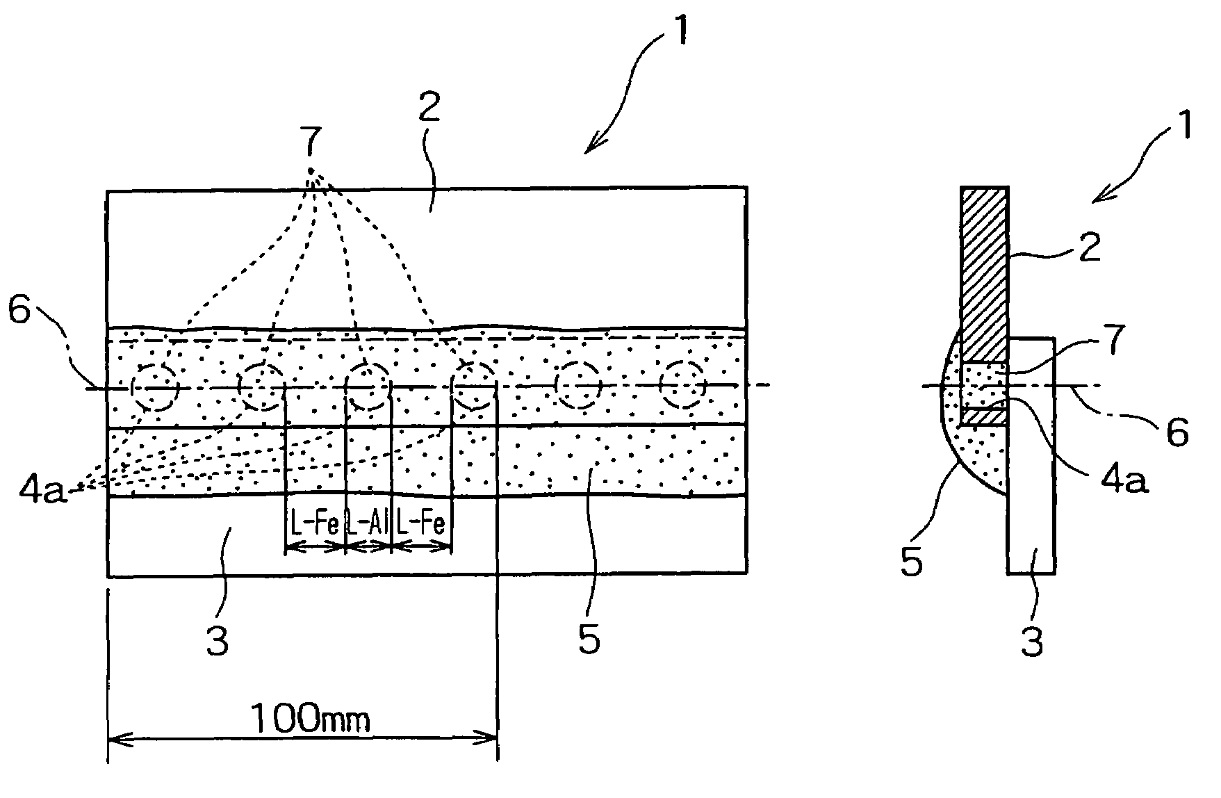
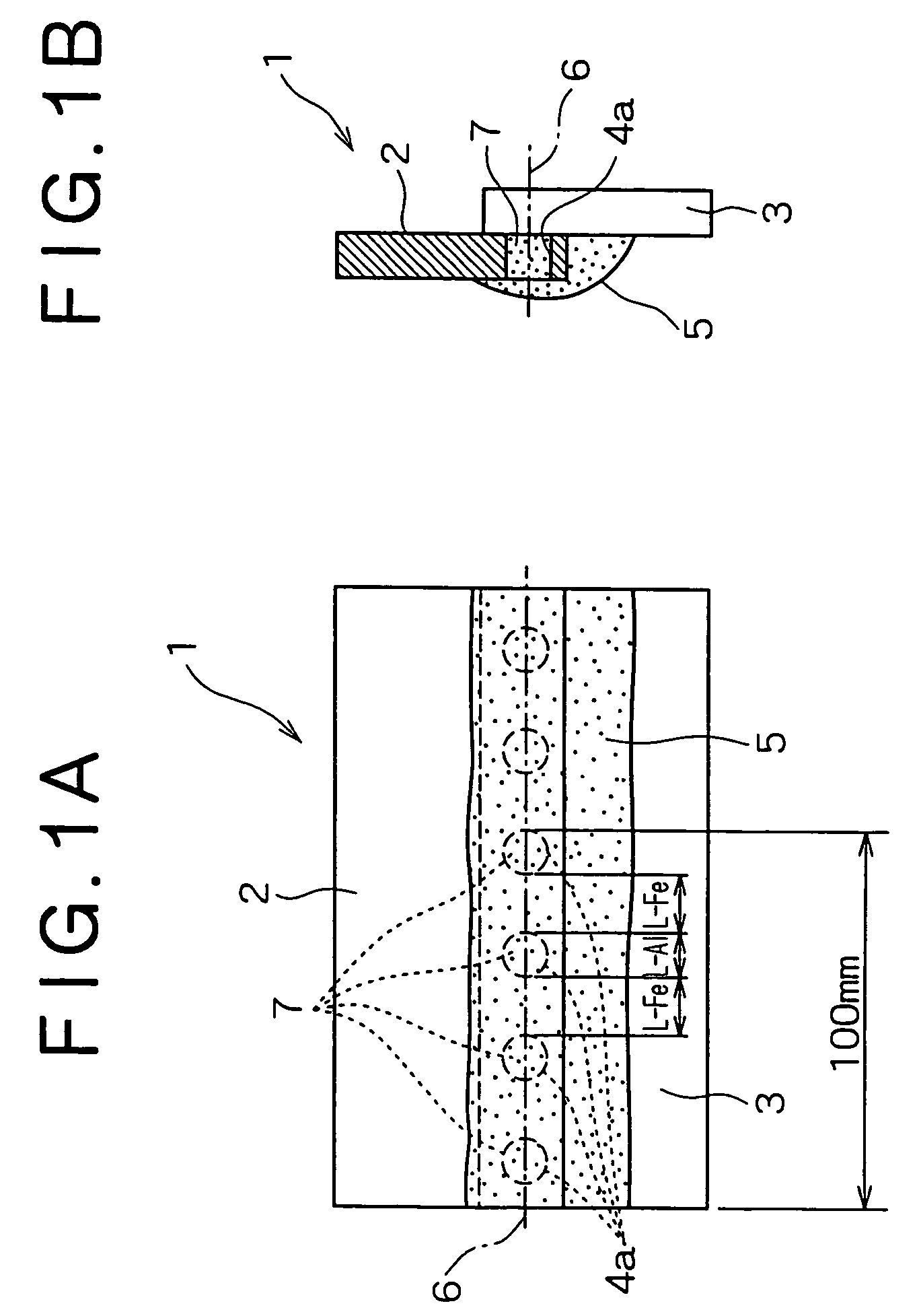
[0078]The present inventors laid a steel sheet (extending from a mild steel sheet SPCE to a high tensile strength steel sheet of up to 980 MPa) in which voids (holes) were formed according to the present invention on an aluminum alloy sheet (A5182), subjected them to lap weld tests using various kinds of aluminum welding wires, thus produced a dissimilar material weld joint, and then evaluated it.

[0079]In Table 1, shown are the conditions (the grade and the thickness) of the steel sheets and the aluminum alloy sheets used in the present weld tests, the welding wire condition (the grade), the welding conditions (the electric current, the voltage and the welding speed), the void conditions (the shape and the parameter P value), the evaluation results (existence of bead cracking and the tensile strength and elongation of the joints), and others. Here, an AC power source was used for all the welding. Then, in order to facilitate the evaluation in the present weld tests, a round shape wa...

example 2

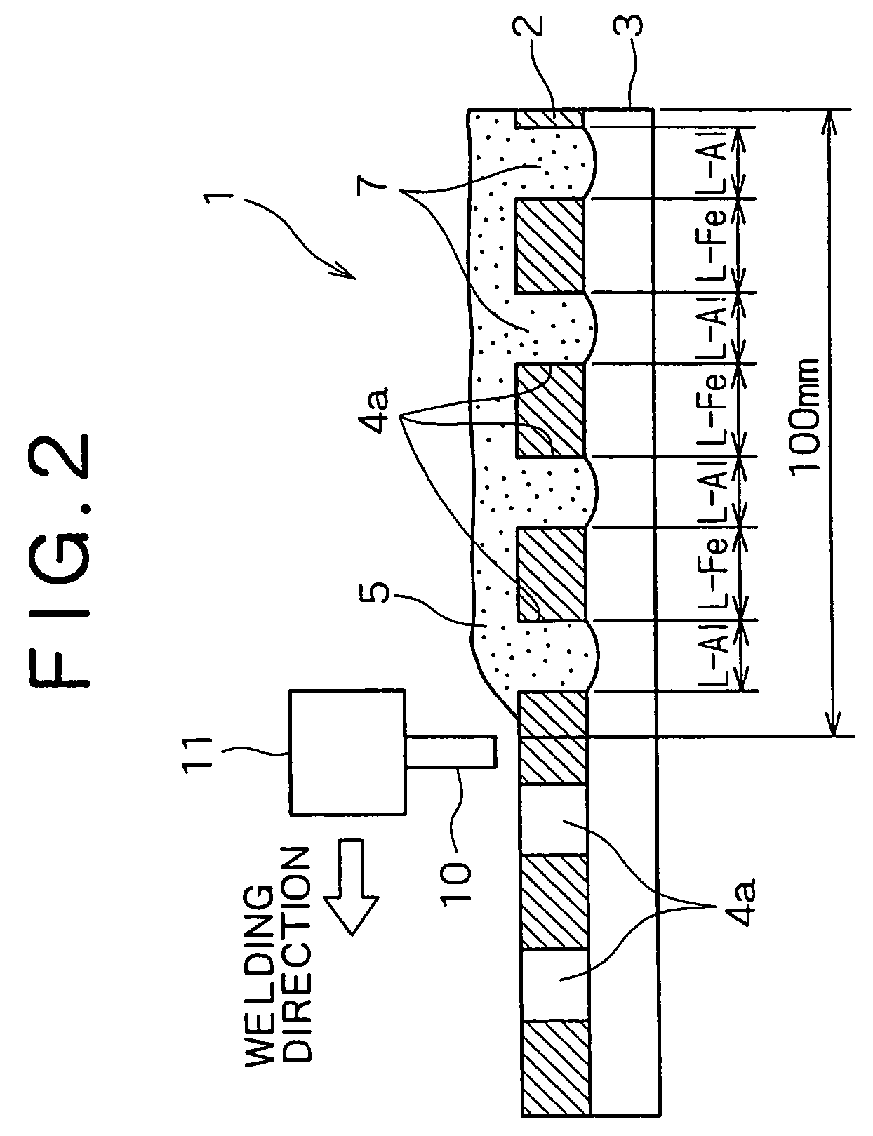
[0088]The present inventors produced weld joints by joining steel sheets (“GA” in the column “Type” meant a hot-dip galvanized steel sheet) and aluminum alloy sheets shown in Table 2 below under various heat input conditions through arc welding using an AC power source and various kinds of aluminum welding wires. In the steel sheets, round-shaped voids of the diameters (2R, R meant a circle-equivalent radius) shown in Table 2 were formed beforehand at the intervals (the lengths of the non-void portions) shown in Table 2. In the arc welding, an Ar gas (flow rate of 20 to 25 l. / min.) was used as the shielding gas. The angle of the welding torch was set at 80°. Here, the Mg contents in the aluminum welding wires used here were as follows; 0.05% or less for A4043-WY, 4.3 to 5.2% for A5183-WY, 4.5 to 5.5% for A5356-WY, and 2.4 to 3.2% for A5554-WY.

[0089]The produced weld joints were visually inspected to judge the existence of bead cracking and also the joint strength thereof was measure...

example 3

[0093]The present inventors produced weld joints by joining steel sheets (“GA” in the column “Type” meant a hot-dip galvanized steel sheet) and aluminum sheets shown in Table 4 below under various heat input conditions through arc welding using a DC power source and various kinds of aluminum welding wires. In the steel sheets, round-shaped voids of the diameters (2R, R meant a circle-equivalent radius) shown in Table 4 were formed beforehand at the intervals (the lengths of the non-void portions) shown in Table 4. In the arc welding, an Ar gas (flow rate of 20 to 25 l. / min.) was used as the shielding gas. The angle of the welding torch was set at 80°.

[0094]The produced weld joints were visually inspected to judge the existence of bead cracking and also the joint strength thereof was measured in the same manner as Example 2. The results are shown in Table 5.

[0095]As it is obvious from Tables 4 and 5, in the case of a DC power source, when the welding condition (heat input Q) satisfie...


PUM

PropertyMeasurementUnit
lengthaaaaaaaaaa
unit lengthaaaaaaaaaa
tensile strengthaaaaaaaaaa

Abstract

Disclosed are: a dissimilar material weld joint being formed by joining an iron type material and an aluminum type material and having not only a high strength but also an excellent ductility; and a weld joining method allowing such a joint to be stably produced. A dissimilar material weld joint 1 formed by joining an iron type material 2 and an aluminum type material 3, wherein: voids 4a are formed beforehand on the side of said iron type material 2 at a predetermined interval along a weld line 6; both said iron type and aluminum type materials are weld joined so that said voids 4a are filled with molten aluminum 7; and the minimum value of the ratio (L-Al) / (L-Fe) of the length (L-Al) of an aluminum type welding material 10 with which said voids 4a are filled to the length (L-Fe) of said iron type material 2 adjacent to said voids 4a filled with said aluminum type welding material 10 along said weld line 6 on the section containing said weld line 6 is in the range from 0.5 to 7, both the lengths (L-Al) and (L-Fe) being the lengths per 100 mm in length of the weld line 6 formed after welding.

Description

BACKGROUND OF THE INVENTION[0001]The present invention relates to a dissimilar material weld joint formed by joining an iron type material and an aluminum type material and a weld joining method, which dissimilar material weld joint is suitably applied to transport vehicles such as automobiles and railway vehicles, machine parts, structural members such as building structures, and the like and is particularly needed when structures for automobiles are fabricated.[0002]If members comprising different kinds of metals (dissimilar material joints) of an iron type material (hereunder referred to simply as “a steel material”) and an aluminum type material (a generic name of pure aluminum and aluminum alloys, and hereunder referred to simply as “an aluminum material”) can be joined, it remarkably contributes to weight reduction and the like. However, when a steel material and an aluminum material are weld joined, brittle intermetallic compounds are likely to form at the weld and therefore ...

Claims


Application Information

Patent Timeline
Patent Type & Authority Patents(United States)
IPC IPC(8): B23K35/24B23K1/19B23K9/23B23K26/32B23K33/00
CPCB23K9/232B23K33/004B23K26/32B23K26/323B23K2203/20Y10T428/12347B23K2203/50B23K2203/08Y10T428/12757B23K2103/18B23K2103/20B23K2103/50B23K2103/10
Inventor TAKEDA, MIKAKOMATSUMOTO, KATSUSHIKINEFUCHI, MASAONAKAGAWA, TOMOKAZUFUKUMOTO, KOJITAKEDA, HIROYUKIMURAI, YASUO
Owner KOBE STEEL LTD
Why Eureka
Try Eureka