
Method of making lamina specimen

a lamina and sample technology, applied in the field of making lamina samples, can solve the problems of inconvenient control of the thickness of the lamina, damage to the lamina sample, and reduced work efficiency, so as to shorten the time required for the work

Active Publication Date: 2010-04-20
HITACHI HIGH TECH SCI CORP
View PDF11 Cites 21 Cited by
  • Summary
  • Abstract
  • Description
  • Claims
  • Application Information

AI Technical Summary

Benefits of technology

[0010]Additionally, there has been adapted such that the working is performed by combining plural focused ion beams, thereby shortening a time required for the working.

Problems solved by technology

In recent years, in various devices such as a semiconductor device and a display device, in order to realize an improvement in function, their structures have become smaller and complicated.
In order to observe this fine structure, although the transmission electron microscope is utilized, in order to observe the fine structure by the high resolving power microscope, there is shown the fact that, when performing a lamina sample making for the observation, damage to the lamina sample when the sputtering etching working by the focused ion beam (FIB) has been performed is made minimum and, at the same time, a shape confirmation of the lamina sample is performed in a scanning electron microscope (SEM) observation by an electron beam irradiation scan.
However, in such a working method, a method of controlling the thickness of the lamina is not known.

Method used


Image

  • Method of making lamina specimen
  • Method of making lamina specimen
  • Method of making lamina specimen

Examples


Embodiment Construction

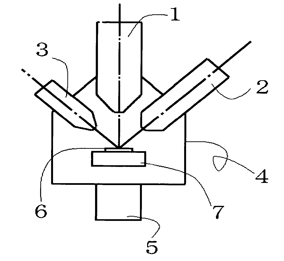
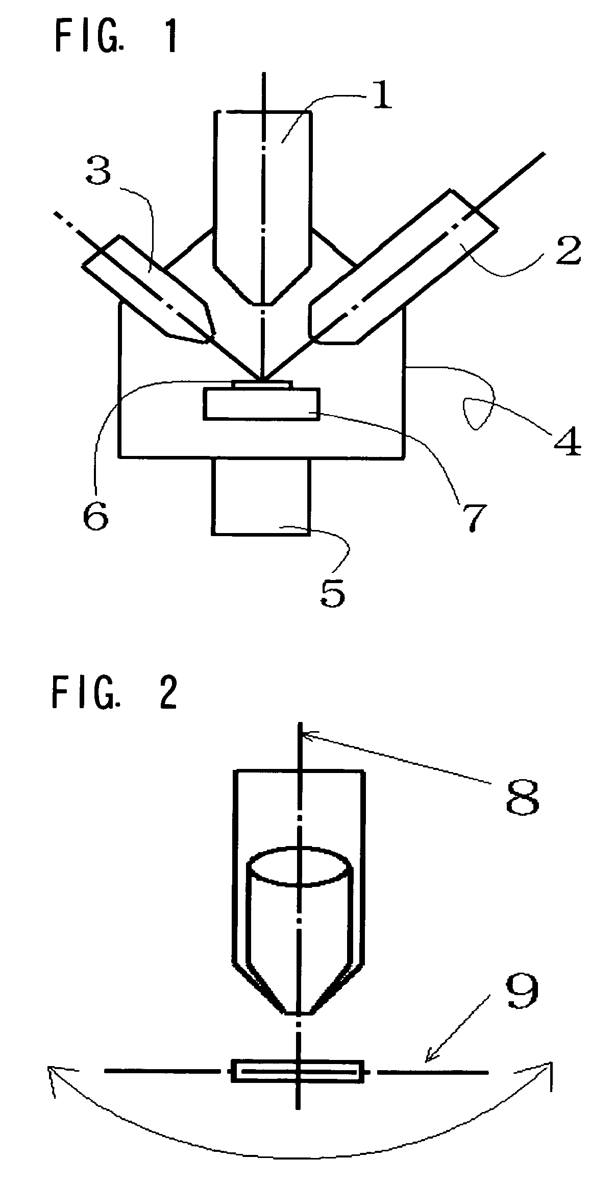
[0027]One embodiment of an apparatus of the present invention is explained by being shown in FIG. 1.

[0028]To a sample chamber 4, there are attached a 1st focused ion beam lens-barrel 1 which focuses ions generating from a liquid metal ion source by a focused ion optical system and scan-irradiates them while being focused to a sample surface, a 2nd focused ion beam lens-barrel 2 which focuses the ions generating from the liquid metal ion source by the focused ion optical system and scan-irradiates them while being focused to the sample surface, and an inert ion beam lens-barrel 3 which generates an inert ion beam such as argon and irradiates it to a sample. An inside of the sample chamber is evacuated by a pump 5, thereby holding a high vacuum state. In an inner side of the sample chamber 4, there is installed a sample stage 7 mounting and moving a sample 6.

[0029]The 1st focused ion beam lens-barrel 1, the 2nd focused ion beam lens-barrel 2, and the inert ion beam lens-barrel 3 are d...


PUM

PropertyMeasurementUnit
thicknessaaaaaaaaaa
intersecting anglesaaaaaaaaaa
voltageaaaaaaaaaa

Abstract

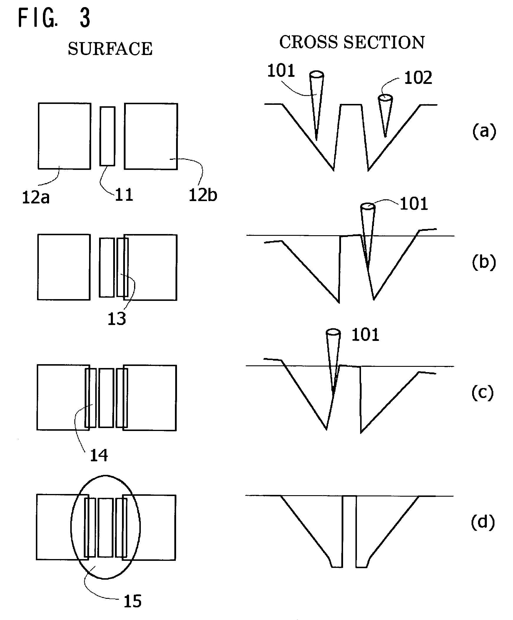
In a method of making a lamina specimen, first and second ion beams are simultaneously used to sputter etch first and second side walls of a lamina region at the same time under first and second ion beam conditions. A scanning ion microscope observation of the lamina region is made using the second ion beam while sputter etching of the first and second side walls is continued using the first ion beam until the thickness of the lamina has a predetermined value.

Description

TECHNICAL FIELD[0001]The present invention relates to a method of making a lamina sample for making the lamina sample for observing by a transmission electron microscope, which forms a lamina in a sample surface of a semiconductor device or the like, and a composite charged particle beam apparatus.BACKGROUND ART[0002]In recent years, in various devices such as a semiconductor device and a display device, in order to realize an improvement in function, their structures have become smaller and complicated. Especially, an element or wiring forming each device becomes a laminated structure in which thin films of several-atom levels have been overlapped, and a demand for observing that structure is high. For this reason, one general technique is that the lamina is taken out by forming it by using a focused ion beam in a sample surface predetermined place, and it is observed by a high resolving power microscope such as transmission electron microscope.[0003]Hitherto, there is known a meth...

Claims


Application Information

Patent Timeline
Patent Type & Authority Patents(United States)
IPC IPC(8): G01N1/00G01N1/28G01N1/32H01J37/20H01J37/30H01J37/304H01J37/305H01J37/317H01L21/302H01L21/66
CPCG01N1/32H01J37/3005H01J37/304H01J37/3056H01J37/3053Y10T436/25H01J2237/31745
Inventor FUJII, TOSHIAKI
Owner HITACHI HIGH TECH SCI CORP
Learn More