Synchronous rectifying circuit for resonant power converters

a technology of synchronous rectifying and power converter, which is applied in the direction of dc-dc conversion, conversion with intermediate conversion to dc, and efficient power electronics conversion, etc., can solve the problems of additional power consumption and achieve the effect of improving the efficiency of resonant power converter

Active Publication Date: 2010-04-20
SEMICON COMPONENTS IND LLC
View PDF8 Cites 30 Cited by
  • Summary
  • Abstract
  • Description
  • Claims
  • Application Information

AI Technical Summary

Benefits of technology

[0008]A synchronous rectifying circuit is developed to improve the efficiency of the resonant power converter. The synchronous rectifying circuit includes a pulse-signal generation circuit for generating a pulse signal in response to the rising edge and the falling edge of a switching signal. The switching signal is utilized to switch a power transformer and regulate the power converter. An isolation device, such as a pulse transformer or capacitors, is coupled to the pulse-signal generation circuit to transfer the pulse signal from the primary side of the power transformer to the secondary side of the power transformer. An integrated synchronous rectifier comprises a rectifying terminal, a ground terminal a first input terminal and a second input terminal. The rectifying terminal is coupled to the secondary side of a power transformer. The ground terminal coupled to the output of the power converter. A power transistor is connected between the rectifying terminal and the ground terminal. The first input terminal and the second input terminal are coupled to receive the pulse signal for turning on / off the power transistor. The pulse signal is a trig signal. The pulse width of the pulse signal is shorter than the pulse width of the switching signal.

Problems solved by technology

However, the disadvantage of this prior art is an additional power consumptions caused by saturable inductors, etc.

Method used


Image

  • Synchronous rectifying circuit for resonant power converters
  • Synchronous rectifying circuit for resonant power converters
  • Synchronous rectifying circuit for resonant power converters

Examples


Embodiment Construction

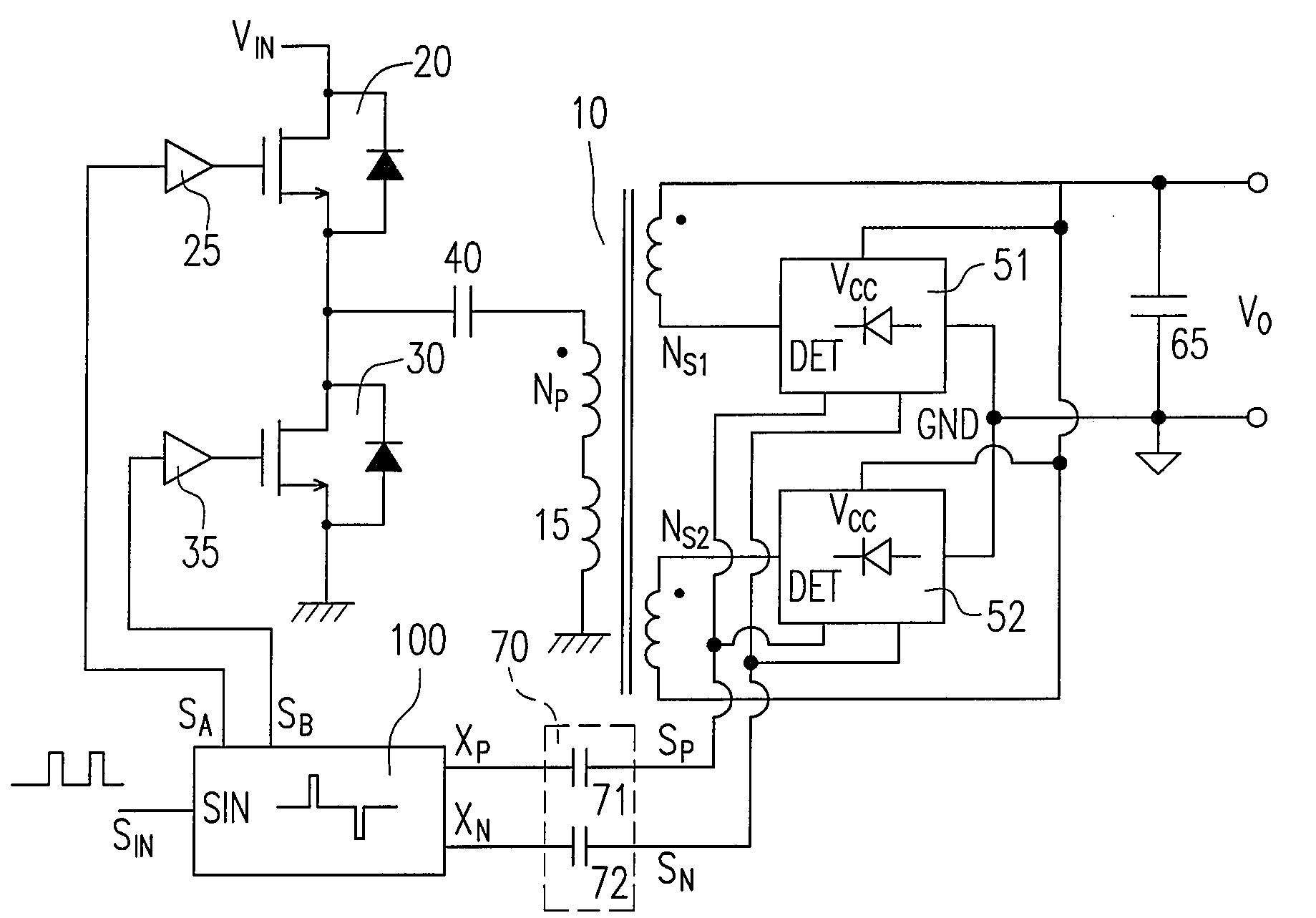
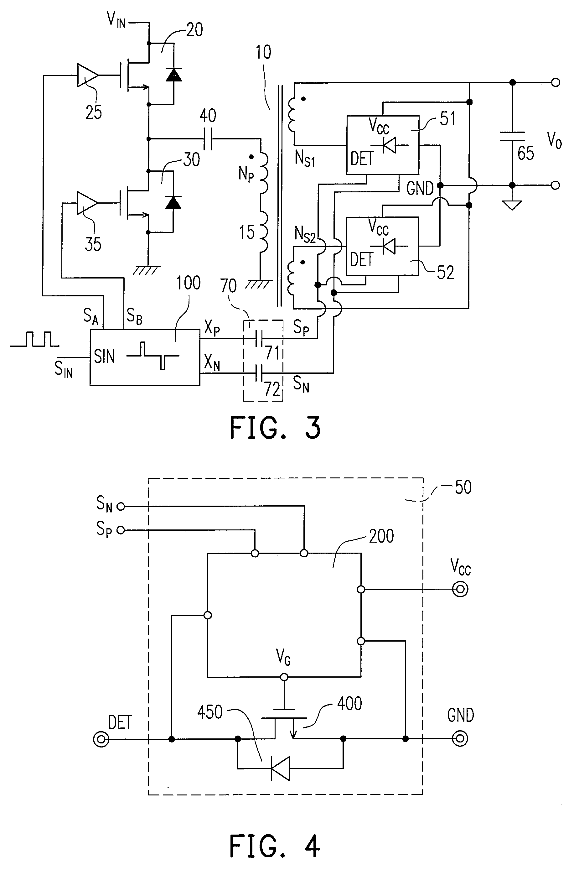
[0021]FIG. 3 shows a resonant power converter with integrated synchronous rectifiers. The resonant power converter includes a power transformer 10 having a primary side and a secondary side. The primary side of the power transformer 10 comprises two power switches 20 and 30 for switching the primary winding NP of the power transformer 10. The secondary side includes a secondary winding NS1 and another secondary winding NS2. A first integrated synchronous rectifier 51 comprises a rectifying terminal DET connected to the secondary winding NS1. A ground terminal GND of the first integrated synchronous rectifier 51 is connected to the ground of the power converter. A second integrated synchronous rectifier 52 having the rectifying terminal DET and the ground terminal GND is also connected from the secondary winding NS2 to the ground of the power converter. A first input terminal SP, a second input terminal SN of the first integrated synchronous rectifier 51 and the second integrated syn...


PUM


Abstract

A synchronous rectifying circuit is provided for resonant power converter. An integrated synchronous rectifier comprises a rectifying terminal, a ground terminal a first input terminal and a second input terminal. The rectifying terminal is coupled to the secondary side of a power transformer. The ground terminal is coupled to the output of the power converter. A power transistor is connected between the rectifying terminal and the ground terminal. The first input terminal and the second input terminal are coupled to receive a pulse signal for turning on / off the power transistor. A pulse-signal generation circuit includes an input circuit coupled to receive the switching signal for switching the power transformer of the power converter.

Description

BACKGROUND OF THE INVENTION[0001]1. Field of Invention[0002]The present invention relates in general to a control circuit of power converter, and more particularly, to synchronous rectifying control circuit for power converters.[0003]2. Description of Related Art[0004]FIG. 1 shows a circuit schematic of an offline resonant power converter. It includes a power transformer 10 to provide isolation from AC line input to the output of the power converter for safety. The soft switching of the resonant power converter achieves high efficiency and low EMI (electric-magnetic interference) performance. Transistors 20 and 30 develop a half bridge circuit to switch a resonant tank. The resonant tank is formed by the power transformer 10, an inductor 15 and a capacitor 40. The inductor 15 acts as a primary-side leakage inductance of the power transformer 10 and / or an inductor device. The inductance L of the inductor 15 and the capacitance C of the capacitor 40 determine the resonance frequency f...

Claims


Application Information

Patent Timeline
Patent Type & Authority Patents(United States)
IPC IPC(8): H02M7/04
CPCH02M3/33592Y02B70/1433Y02B70/1491H02M2001/0058Y02B70/1475Y02B70/10H02M1/0058
Inventor YANG, TA-YUNGCHEN, TSO-MIN
Owner SEMICON COMPONENTS IND LLC
Why Eureka
Try Eureka