Submersible portable in-situ automated water quality biomonitoring apparatus and method

a biomonitoring and water quality technology, applied in the direction of liquid/fluent solid measurement, machines/engines, instruments, etc., can solve the problems of heavy and cumbersome transportation, difficult to determine the actual occurrence of coughing, and large mobile facility

Inactive Publication Date: 2010-04-20
UNITED STATES OF AMERICA THE AS REPRESENTED BY THE SEC OF THE ARMY
View PDF5 Cites 5 Cited by
  • Summary
  • Abstract
  • Description
  • Claims
  • Application Information

AI Technical Summary

Benefits of technology

[0012]The present invention overcomes the practical problems described above and provides additional advantages as well. The present invention is based, in part, on the discovery that the use of specifically-proportioned biomonitoring chambers made of a dielectric material allows for receipt of signals of sufficient quality for biomonitoring water quality in-situ.
[0013]Accordingly, one object of the present invention is to provide a submersible apparatus for automated biomonitoring of water quality. A related aspect of the invention is to provide embodiments of the submersible system that eliminate the need for pumps, tubing, temperature control, filtration, water manifolds, and the like currently used for monitoring water quality. One advantageous feature of at least one embodiment of the invention is that the submersible design overcomes the affects caused by water loss due to mechanical failure found in land-based systems. Another advantageous feature of at least one embodiment of the invention is the reduction in power requirements to run a submersible system as opposed to a land-based system requiring pumps and the like. In accordance with one embodiment of the invention, the power requirement is reduced from several amps to less than 0.5 amps for 16 amplifiers. Accordingly, an object of the invention is to provide a submersible system for monitoring water quality that allows for solar powered operation.
[0014]An additional related aspect of the invention is to provide a low cost alternative to land-based monitoring systems, wherein the savings in having reduced architecture to run the system allows for multiple monitoring sights to be deployed at the same price as it would cost to operate one fixed sight. An advantageous feature of this aspect of the invention is use of the system to deploy an in-stream network of monitoring units that could track developing toxic conditions in a watershed or along the length of a stream or river. As will be appreciated, having numerous data collection areas in a body of water provides substantial benefits in detecting, pinpointing, and remediating a source of contamination over a single fixed facility.

Problems solved by technology

Cough rate has been more difficult to determine even with manual examination of a strip chart as several different types of coughs may be present, with their own corresponding characteristic waveform pattern.
Also, without the use of simultaneous video techniques, the actual occurrence of a cough is not always clear.
However, the nature and size of water monitoring equipment typically prevents such field testing.
The mobile facility is somewhat large, heavy and cumbersome to transport.
While the biomonitor cabinet greatly reduces size and weight requirements, it still requires a fixed facility for installation and use.
However, the construction of a submersible or in-situ monitoring device has proven problematic.
For reasons not easily explained, there exists a physical phenomenon whereby signals generated by fish in a submersed monitoring chamber are incapable of being received in a quality sufficient for biomonitoring.
Most prior artisans agree that pursuit of a submersible monitoring chamber is a lost cause due to this inability to receive suitable signals from fish in a submersed exposure chamber.

Method used


Image

  • Submersible portable in-situ automated water quality biomonitoring apparatus and method
  • Submersible portable in-situ automated water quality biomonitoring apparatus and method
  • Submersible portable in-situ automated water quality biomonitoring apparatus and method

Examples


Embodiment Construction

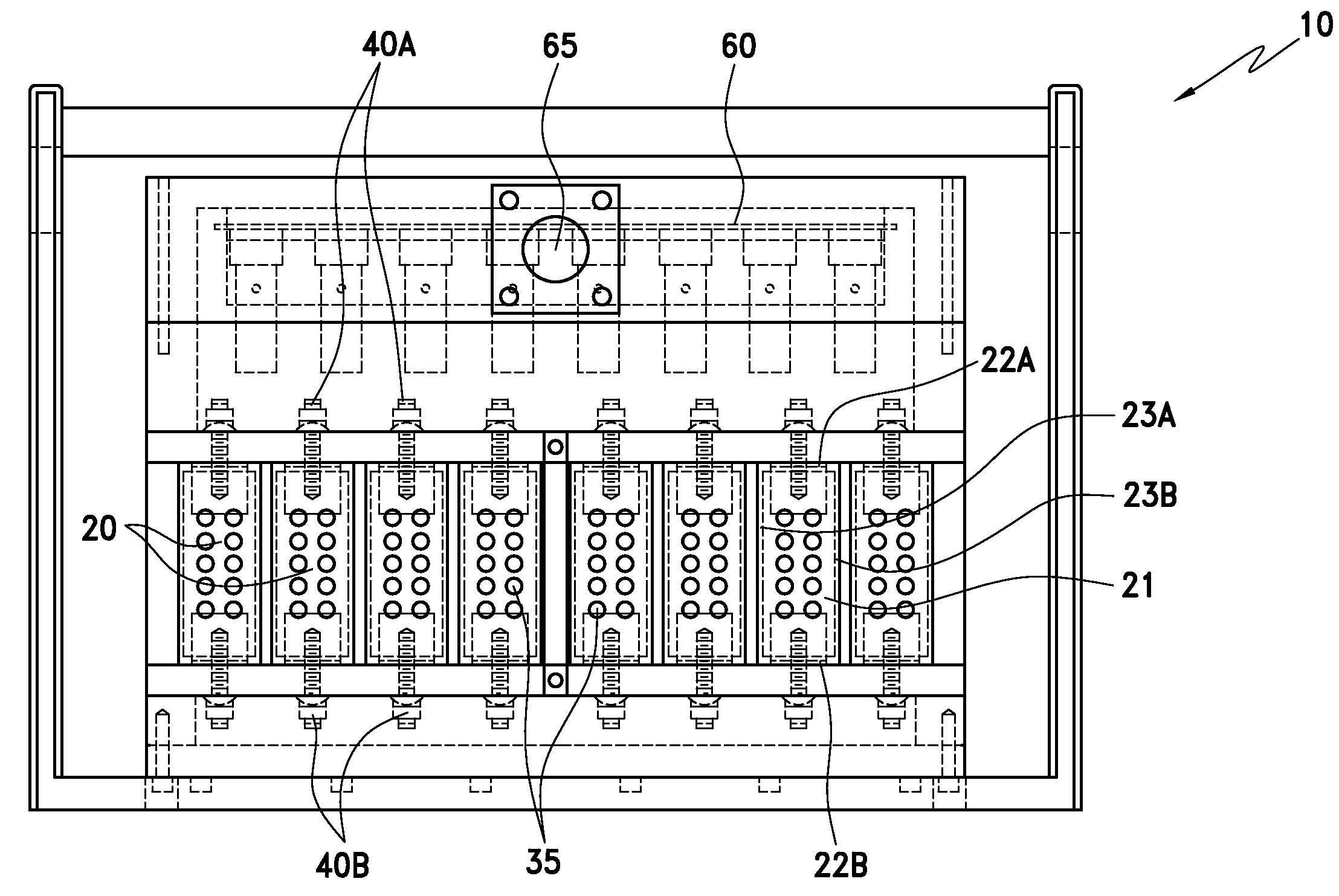
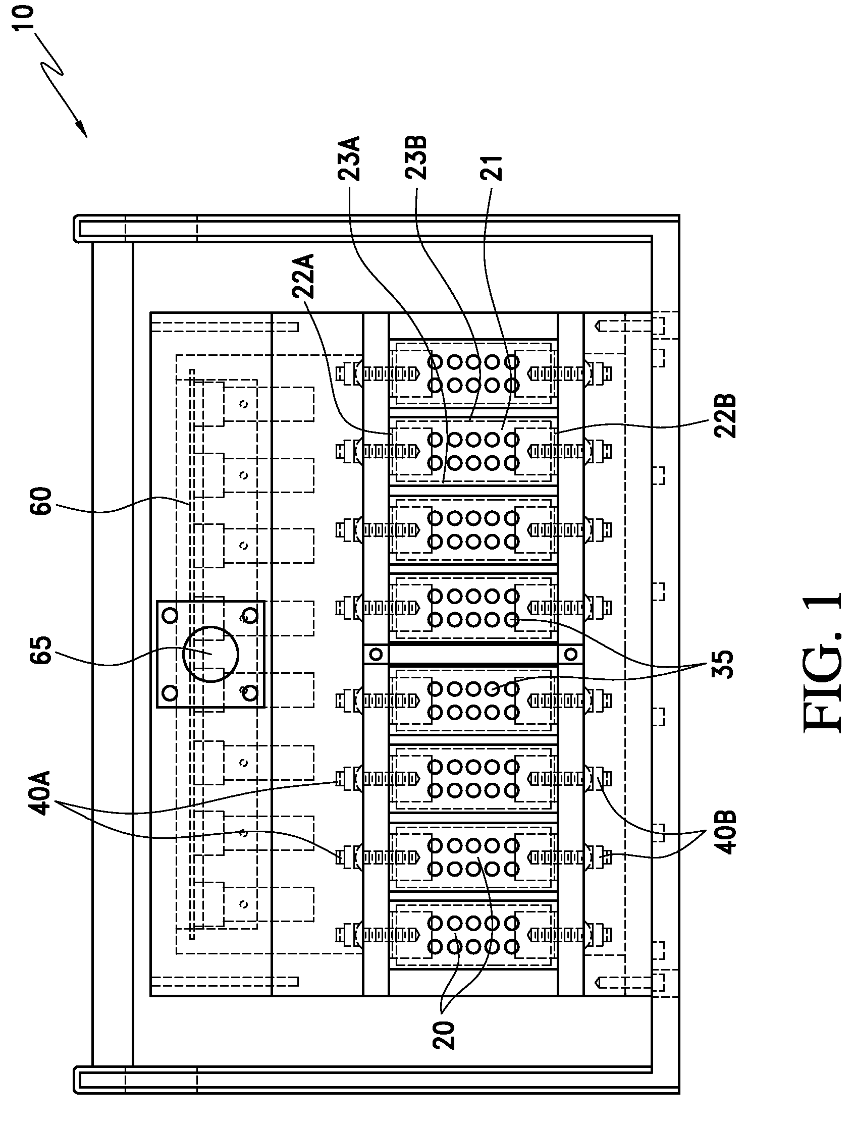
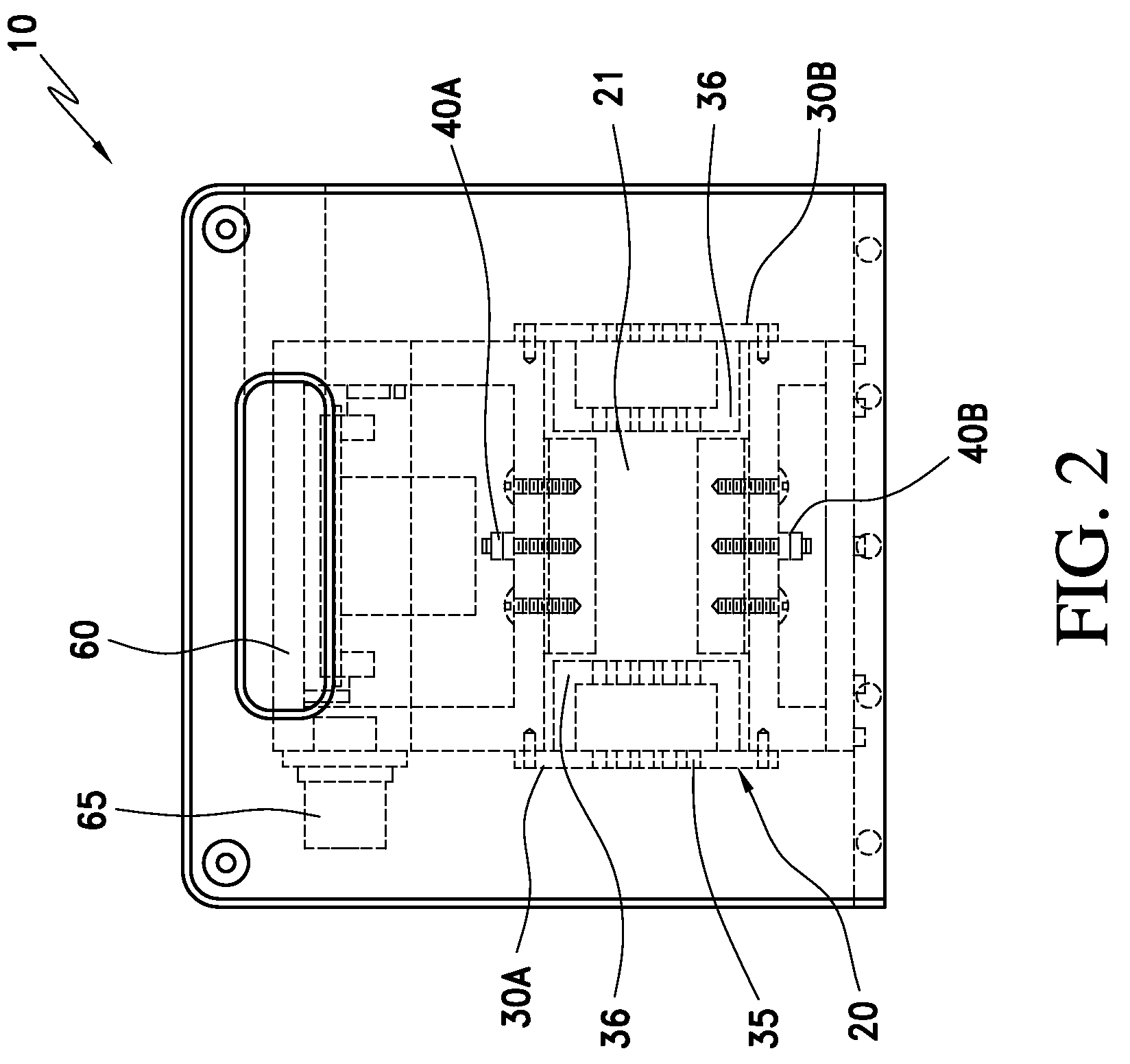
[0035]As previously mentioned, the present invention is based, in part, on the discovery that the use of specifically-proportioned chambers and cells made of a dielectric material allows for receipt of signals of sufficient quality for biomonitoring water quality in-situ. While the present invention will be described in connection with a submersible in situ chamber for biomonitoring water quality, it will be readily apparent to one of ordinary skill in the art that the present invention can be applied to a multiplicity of fields and uses, including other areas where cross-talk or the inability to assure reliable ambient conditions are needed. Furthermore, while the present invention will be described in connection with the use of certain specific aquatic species, one of ordinary skill in the art will recognize the interchangeability and ease to which the device can be used with alternative species. Finally, while the present invention will be described in connection with a single su...


PUM

PropertyMeasurementUnit
lengthaaaaaaaaaa
lengthaaaaaaaaaa
conductivityaaaaaaaaaa

Abstract

A submersible biomonitoring system for monitoring water quality in situ includes a submersible chamber constructed of a di-electric material and sized to allow suitable signals from one or more aquatic organisms to be received by eliminating cross-talk between cells while allowing ambient conditions to be maintained inside the chamber. The aquatic organism exhibits ventilatory behavior and body movement sensitive to water quality which manifest as electrical signals picked up by electrodes and communicated to a pre-amplifier that conditions the signals for communication to a land-based amplifier and / or controller that is used to interpret the signals to determine when the water to which the organism is exposed has caused physiological stress to the organism.

Description

I. FIELD OF THE INVENTION[0001]The present invention relates generally to an apparatus and method for monitoring water quality. More particularly, the present invention relates to a submersible apparatus and in-situ method for monitoring water quality using the ventilatory behavior and body movement of aquatic organisms.II. BACKGROUND OF THE INVENTION[0002]Ventilatory responses are often some of the first prelethal symptoms exhibited by animals to environmental stressors. Continued, abnormal ventilatory behavior, such as rapid, shallow, or erratic breathing, can indicate physiological damage that may be irreversible. Changes in the ventilatory behavior of fish have been shown to be a reliable indicator of accidental toxic spills or “slugs” of pollutants in wastewater and drinking water systems. Accordingly, ventilatory biomonitoring systems can serve as an early indicator of impending damage to aquatic ecosystems and possible harm to humans.[0003]The technological means are readily ...

Claims


Application Information

Patent Timeline
Patent Type & Authority Patents(United States)
IPC IPC(8): G01N11/00
CPCG01N33/186G01N33/1886
Inventor WIDDER, MARK W.SHEDD, TOMMY R.BROWN, MARK W.SWANSON, MURRAY S.
Owner UNITED STATES OF AMERICA THE AS REPRESENTED BY THE SEC OF THE ARMY
Why Eureka
Try Eureka