Electromechanical memory devices and methods of manufacturing the same

a technology of electronic mechanical memory and manufacturing methods, applied in semiconductor devices, electrical devices, semiconductor/solid-state device details, etc., can solve the problems of poor data retention reliability, low operating speed of flash memory, and relatively short life span, and achieve enhanced data retention, high long-term endurance, and high speed operation

Inactive Publication Date: 2010-04-27
SAMSUNG ELECTRONICS CO LTD
View PDF3 Cites 2 Cited by
  • Summary
  • Abstract
  • Description
  • Claims
  • Application Information

AI Technical Summary

Benefits of technology

[0005]Embodiments of the present invention are directed to electromechanical memory devices and methods of manufacture thereof that address and alleviate the above-identified limitations of conventional devices. In particular, embodiments of the present invention provide electromechanical memory devices that realize, among other features, high-density storage, low-voltage program and erase voltages, high-speed operation, enhanced data retention, and high long-term endurance, and methods of formation of such devices. The embodiments of the present invention are applicable to both non-volatile and volatile memory device formats.

Problems solved by technology

One type of non-volatile device, referred to as flash memory, has become popular because it is relatively inexpensive to produce, and because it operates at relatively low power demands; however, flash memory is known to generally suffer from low operating speed, relatively poor data retention reliability and relatively short life span.
In addition, such devices are based on the operation of conventional transistors, and with the pressures of further integration, they increasingly suffer from the short-channel effect, lowering of breakdown voltage, and lowering of reliability of the gate junction with repeated program / erase cycles.
In addition, as the size of the transistor decreases, there is an increased likelihood of intercell interference, which can have a further adverse effect on performance and reliability.

Method used


Image

  • Electromechanical memory devices and methods of manufacturing the same
  • Electromechanical memory devices and methods of manufacturing the same
  • Electromechanical memory devices and methods of manufacturing the same

Examples


Embodiment Construction

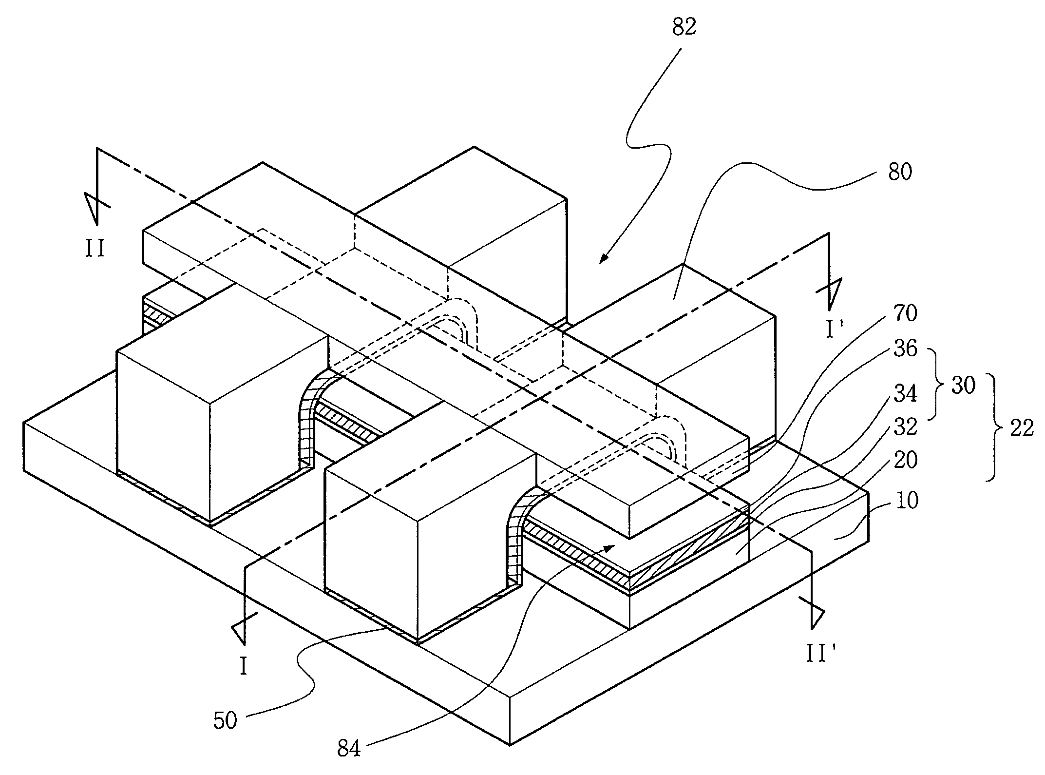
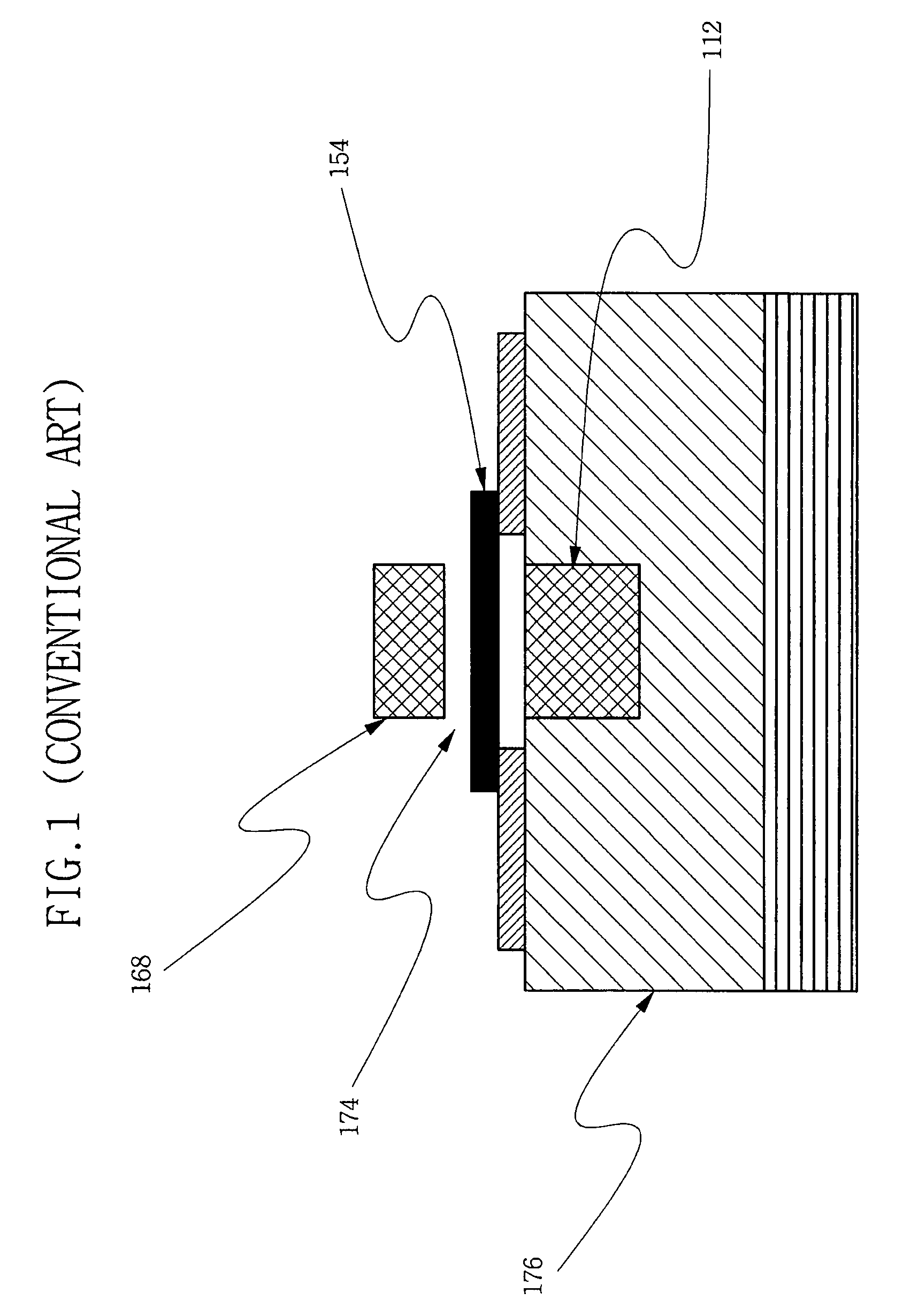
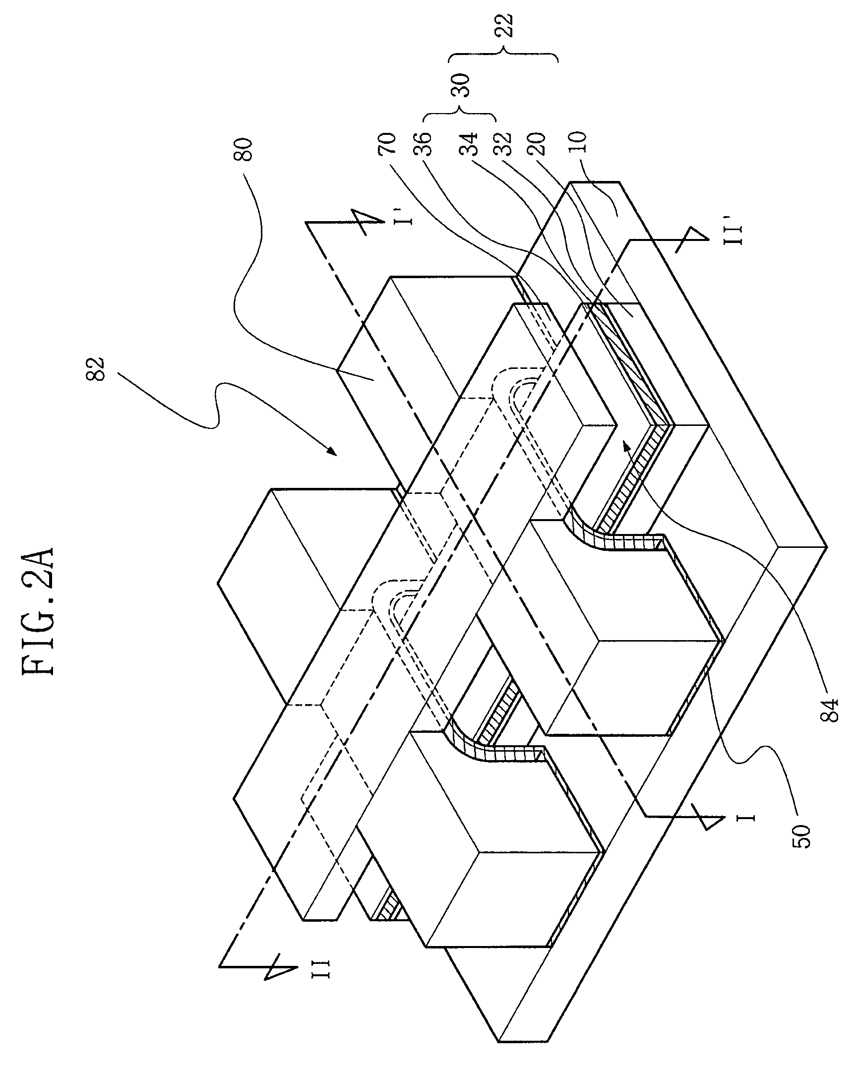
[0102]Embodiments of the present invention will now be described more fully hereinafter with reference to the accompanying drawings, in which preferred embodiments of the invention are shown. This invention may, however, be embodied in different forms and should not be construed as limited to the embodiments set forth herein. Like numbers refer to like elements throughout the specification.

[0103]It will be understood that, although the terms first, second, etc. are used herein to describe various elements, these elements should not be limited by these terms. These terms are used to distinguish one element from another. For example, a first element could be termed a second element, and, similarly, a second element could be termed a first element, without departing from the scope of the present invention. As used herein, the term “and / or” includes any and all combinations of one or more of the associated listed items.

[0104]It will be understood that when an element is referred to as b...


PUM


Abstract

In a memory device and a method of forming the same, in one embodiment, the memory device comprises a first word line structure on a substrate, the first word line structure extending in a first direction. A bit line is provided over the first word line structure and spaced apart from the first word line by a first gap, the bit line extending in a second direction transverse to the first direction. A second word line structure is provided over the bit line and spaced apart from the bit line by a second gap, the second word line structure extending in the first direction. The bit line is suspended between the first word line structure and the second word line structure such that the bit line deflects to be electrically coupled with a top portion of the first word line structure through the first gap in a first bent position and deflects to be electrically coupled with a bottom portion of the second word line structure through the second gap in a second bent position, and is isolated from the first word line structure and the second word line structure in a rest position.

Description

RELATED APPLICATIONS[0001]This application claims priority under 35 U.S.C. 119 to Korean Patent Application No. 10-2006-0074015 filed on Aug. 7, 2006, the content of which is incorporated herein by reference in its entirety.[0002]This application is related to U.S. patent application Ser. No. 11 / 713,770, filed Mar. 2, 2007, entitled “Multi-bit Electromechanical Memory Devices and Methods of Manufacturing the Same,” by Yun, et al., filed of even date herewith, incorporated herein by reference, and commonly owned with the present application.BACKGROUND OF THE INVENTION[0003]Semiconductor memory devices include memory cells for the storage of electronic information. Non-volatile memory devices enjoy widespread use because their associated memory cells can retain information even when the source power supply is disabled or removed. This feature makes non-volatile memory devices especially attractive for use in portable electronics. With the continuous trend toward higher integration, hi...

Claims


Application Information

Patent Timeline
Patent Type & Authority Patents(United States)
IPC IPC(8): H01L29/78
CPCH01L27/10H01L2924/0002H01L2924/00H01L29/40117H10B63/80H10B43/30
Inventor YUN, EUNJUNGLEE, SUNG-YOUNGKIM, DONG-WON
Owner SAMSUNG ELECTRONICS CO LTD
Why Eureka
Try Eureka