Resonant converter with synchronous rectification drive circuit

a synchronous and drive circuit technology, applied in the direction of electric variable regulation, process and machine control, instruments, etc., can solve the problems of high cost, energy waste, failure of the llc series resonant converter in the second frequency region region-b>2/b>, etc., and achieve the effect of reducing the turn-off period

Inactive Publication Date: 2010-04-27
TUNGNAN INST TECH
View PDF10 Cites 27 Cited by
  • Summary
  • Abstract
  • Description
  • Claims
  • Application Information

AI Technical Summary

Benefits of technology

[0019]It is an aspect of the present invention to provide a resonant converter with a synchronous rectification drive circuit including a switch circuit, a resonant circuit, a transformer, a full-wave-rectifier circuit and a synchronous rectification drive circuit, wherein the synchronous rectification drive circuit includes four voltage-clamped drive circuits respectively coupled to the switch circuit and the full-wave-rectifier circuit, and each voltage-clamped drive circuit includes a clamp circuit and a transmission / discharge circuit for reducing the turn-off period of the switch, so as to increase the efficiency of the resonant converter when the switch circuit and the full-wave-rectifier circuit are turned off.
[0021]In accordance with the present invention, the resonant converter with a synchronous rectification drive circuit includes a switch circuit having at least one bridge arm having a first switch and a second switch; a resonant circuit coupled to the switch circuit and having a resonant frequency; a transformer having a primary side coupled to the resonant circuit and a secondary side; a full-wave-rectifier circuit coupled to the secondary side and having a third switch and a fourth switch; and a synchronous rectification drive circuit having a first voltage-clamped drive circuit, a second voltage-clamped drive circuit, a third voltage-clamped drive circuit and a fourth voltage-clamped drive circuit, wherein output terminals of the voltage-clamped drive circuits are coupled to the first switch, the second switch, the third switch and the fourth switch, respectively, and each of the voltage-clamped drive circuits includes a transmission / discharge circuit for reducing a turn-off period of the coupled switches during turning off the coupled switches.
[0029]In accordance with the present invention, the resonant converter with a synchronous rectification drive circuit includes a first isolator having a first input terminal coupled to a drive signal producing device for receiving a first phase signal and having a first output terminal coupled to the fourth voltage-clamped drive circuit for preventing the first phase signal from being interfered by a first signal from the fourth voltage-clamped drive circuit, and the resonant converter with a synchronous rectification drive circuit further includes a second isolator having a second input terminal coupled to the drive signal producing device for receiving a second phase signal and having a second output terminal coupled to the third voltage-clamped drive circuit for preventing the second phase signal from being interfered by a second signal from the third voltage-clamped drive circuit.

Problems solved by technology

However, under the identical conditions, the operation of the LLC series resonant converter in the second frequency region Region-2 fails if the LLC series resonant converter uses the MOSFET as the rectification switch.
Therefore, the cost is high and the energy is wasted owing to ignoring to increase the conversion efficiency.

Method used


Image

  • Resonant converter with synchronous rectification drive circuit
  • Resonant converter with synchronous rectification drive circuit
  • Resonant converter with synchronous rectification drive circuit

Examples


Embodiment Construction

[0046]The invention is described more specifically with reference to the following embodiments. It is to be noted that the following descriptions of preferred embodiments of this invention are presented herein for the purpose of illustration and description only; it is not intended to be exhaustive or to be limited to the precise form disclosed.

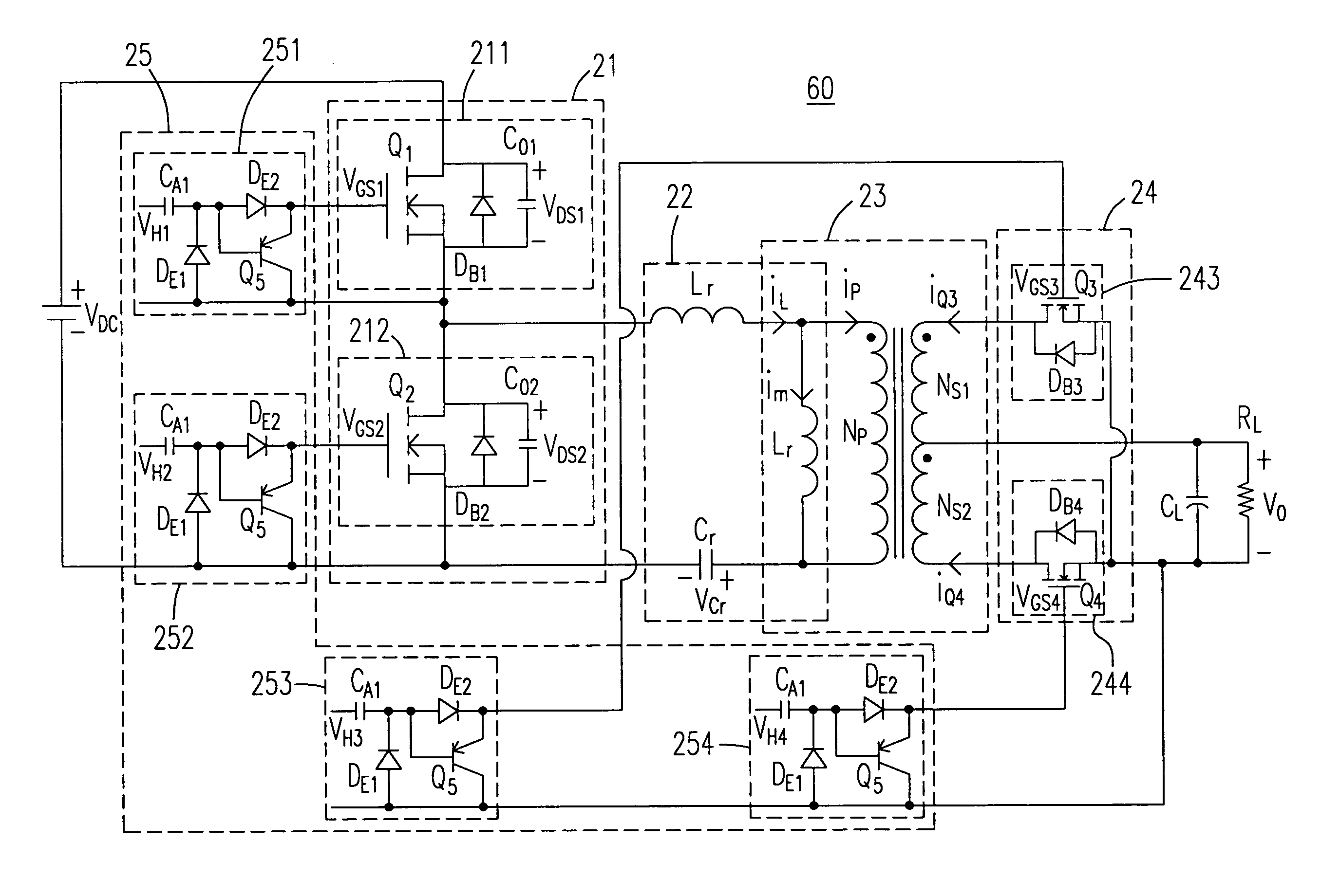
[0047]Please refer to FIG. 3 showing a resonant converter with a synchronous rectification drive circuit according to a preferred embodiment of the present invention. In the figures, similar components are denoted as similar reference numbers. It is to be noted that a switch circuit 21 of an input terminal is composed of a half-bridge circuit having a bridge arm in FIG. 3. Alternatively, the switch circuit 21 of the input terminal can be composed of a full-bridge circuit having two bridge arms. The resonant converter 60 has a synchronous rectification drive circuit 25 for implementing the synchronous rectification drive of the present inventi...


PUM


Abstract

The present invention provides a resonant converter with a synchronous rectification drive circuit. The resonant converter with the synchronous rectification drive circuit includes a switch circuit, a resonant circuit, a transformer, a full-wave-rectifier circuit and a synchronous rectification drive circuit, wherein the switch circuit at least includes a half-bridge circuit, the resonant circuit is coupled to the switch circuit and has a resonant frequency, the transformer has a primary side coupled to the resonant circuit, the full-wave-rectifier circuit is coupled to a secondary side of the transformer and includes two switches, the synchronous rectification drive circuit includes four voltage-clamped drive circuits having output terminals coupled to the switch circuit and the corresponding switch of the full-wave-rectifier circuit, and each voltage-clamped drive circuit includes a transmission / discharge circuit for reducing the turn-off period of the coupled switch during turning off the coupled switch.

Description

FIELD OF THE INVENTION[0001]This invention relates to a resonant circuit with a synchronous rectification drive circuit, and more particular to an LLC series resonant converter in a power supply.BACKGROUND OF THE INVENTION[0002]Recently, the trend of the electronic equipments is toward the application with low voltage and high current. The power management technology is developed from the rectification of the rectification diode to the synchronous rectification of the metal-oxide-semiconductor field-effect transistor (MOSFET). The power consumed in the equipment with the rectification diode is more than that consumed in the equipment with the MOSFET; moreover, the performance of the switching power supply can be increased by the latter. The MOSFET is used for the power supply of the LCD TV with low noise and high efficiency and for the power supply of the computer and the telecommunication equipments.[0003]Please refer to FIG. 1(a) showing the circuit of the rectification diode type...

Claims


Application Information

Patent Timeline
Patent Type & Authority Patents(United States)
IPC IPC(8): H02M3/335
CPCH02M3/33592Y02B70/1433Y02B70/1491H02M2001/0058Y02B70/1475H02M1/0058Y02B70/10H02M1/08
Inventor HSIEH, GUAN-CHYUNHSU, WEI-LITSAI, CHENG-YUAN
Owner TUNGNAN INST TECH
Why Eureka
Try Eureka