Magnetic bead-based sample separating device
a magnetic bead and sample technology, applied in the separation process, laboratory glassware, instruments, etc., can solve the problems of high labor intensity, long operating time, complicated operating procedures, etc., and achieve the effect of reducing pollution risk, increasing the extraction rate of magnetic beads, and enhancing the extraction of magnetic beads
- Summary
- Abstract
- Description
- Claims
- Application Information
AI Technical Summary
Benefits of technology
Problems solved by technology
Method used
Image
Examples
first embodiment
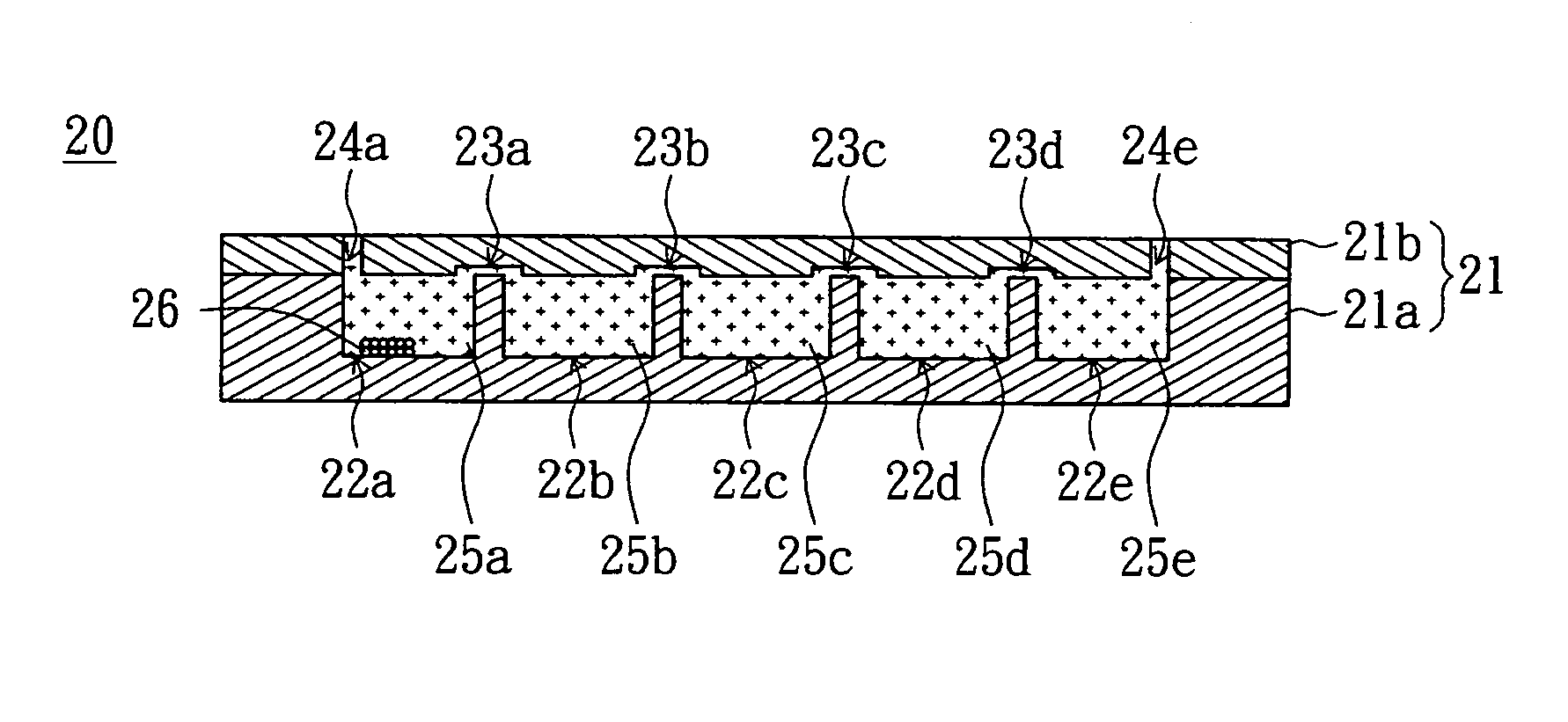
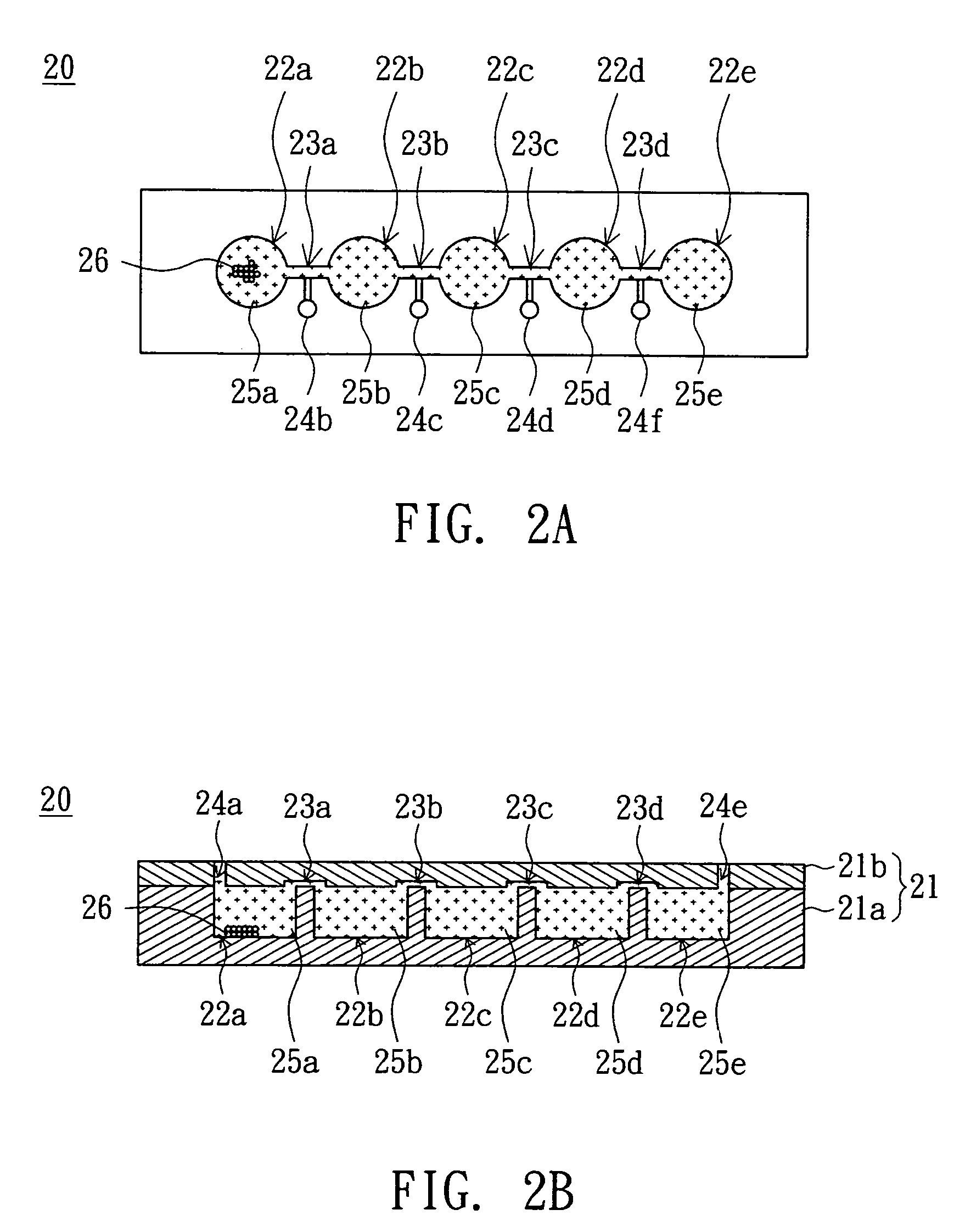
[0030]Referring to both FIGS. 2A and 2B, FIG. 2A is a top view of a magnetic bead-based sample separating device according to a first embodiment of the invention, and FIG. 2B is a horizontal cross-sectional view of a magnetic bead-based sample separating device in FIG. 2A. The magnetic bead-based sample separating device 20 includes a body 21, five reactors 22a˜22e and four micro-channels 23a˜23d. The body 21 has six openings 24a˜24f. The reactors 22a˜22e are disposed in the body 21. The reactor 22a, exemplified by the first reactor, is used for receiving a mixing solution 25a. The mixing solution 25a at least includes several magnetic beads 26 and a sample extraction. The sample extraction is bound with the magnetic beads 26. The reactor 22b, exemplified by the second reactor, is used for receiving a washing buffer 25b. The reactor 22c is used for receiving a washing buffer 25c. The reactor 22d is used for receiving a washing buffer 25d. The reactor 22e, exemplified by the third re...
second embodiment
[0039]Referring to both FIGS. 6A˜6C, FIG. 6A is a top view of a magnetic bead-based sample separating device according to a second embodiment of the invention, FIG. 6B is a vertical cross-sectional view of a magnetic bead-based sample separating device in FIG. 6A, and FIG. 6C is a horizontal cross-sectional view of a magnetic bead-based sample separating device in FIG. 6A. It is noted that FIG. 6B is a cross-sectional view of the rightmost column of the reactor and the micro-channel in FIG. 6A, and FIG. 6C is a cross-sectional view of the topmost column of the reactor and the micro-channel in FIG. 6A. The magnetic bead-based sample separating device 30 includes a reactor array base 40 and a micro-channel array cover 50. The reactor array base 40 includes a base body 41, two reactors 42a and 42b (such as the first reactor) arranged in the same row, two reactors 43a and 43b (such as the second reactor) arranged in the same row, two reactors 44a and 44b arranged in the same row, and tw...
third embodiment
[0052]Referring to FIG. 8, a top view of a magnetic bead-based sample separating device according to a third embodiment of the invention is shown. The magnetic bead-based sample separating device 90 includes a reactor array base 70 and a micro-channel array cover 80. The reactor array base 70 of the present embodiment of the invention can be augmented from the reactor array base 40 of the second embodiment to have more than two rows of reactors. For example, the reactor array base 70 has four rows of reactors, and each row has five reactors. Moreover, the micro-channel array cover 80 of the present embodiment of the invention can also be augmented from the micro-channel array cover 50 of the second embodiment to have more than two rows of vertical micro-channels and more than one row of horizontal micro-channels. For example, the micro-channel array cover 80 can have four rows of vertical micro-channel with each row having four vertical micro-channels, and three rows of horizontal m...
PUM
| Property | Measurement | Unit |
|---|---|---|
| Time | aaaaa | aaaaa |
| Diameter | aaaaa | aaaaa |
| Diameter | aaaaa | aaaaa |
Abstract
Description
Claims
Application Information
 - R&D
- Intellectual Property
- Life Sciences
- Materials
- Tech Scout
- Unparalleled Data Quality
- Higher Quality Content
- 60% Fewer Hallucinations
Browse by: Latest US Patents, China's latest patents, Technical Efficacy Thesaurus, Application Domain, Technology Topic, Popular Technical Reports.
© 2025 PatSnap. All rights reserved.Legal|Privacy policy|Modern Slavery Act Transparency Statement|Sitemap|About US| Contact US: help@patsnap.com


