Method and system for allocating traffic demands in a ring network

a traffic demand and ring topology technology, applied in the field of communication network management, can solve the problems of increasing data traffic demand, challenging the capacity limits of these existing transport infrastructures, and affecting the efficiency of sonet-based networks in utilizing available bandwidth

Active Publication Date: 2010-05-04
VERIZON PATENT & LICENSING INC
View PDF13 Cites 13 Cited by
  • Summary
  • Abstract
  • Description
  • Claims
  • Application Information

AI Technical Summary

Benefits of technology

[0012]In accordance with an additional aspect of the present invention, a Resilient Packet Ring system is disclosed. The system comprises a plurality of stations interconnected by segments in a ring topology, each of the stations capable of transmitting and receiving traffic demands in a first direction and a second direction. The system further comprises a first ring comprising a first set of segments for transmitting and receiving traffic demands in the first direction, and a second ring comprising a second set of segments for transmitting and receiving traffic demands in the second direction. The system also comprises a traffic management system for sequentially routing a plurality of traffic demands on the first and second rings to provide the smallest incremental increase in the maximum load of the first and second sets of segments.

Problems solved by technology

The rapidly increasing demand for data traffic, however, is challenging the capacity limits of these existing transport infrastructures.
This is compounded by the fact that SONET-based networks generally utilize available bandwidth inefficiently.
Such fixed allocation puts a limit on the maximum burst data-transfer rate between endpoints, which is a disadvantage for data traffic because data traffic is inherently bursty.
Thus, while Ethernet switches can provide link-level fairness, this does not necessarily or easily translate into global fairness.
Consequently, neither SONET nor Ethernet effectively manages a shared resource such as a fiber ring shared across thousands of potential subscribers.
More particularly, the network is underutilized in the case of SONET and non-deterministic in the case of Ethernet.
However, RPR rings are still subject to becoming poorly routed.

Method used


Image

  • Method and system for allocating traffic demands in a ring network
  • Method and system for allocating traffic demands in a ring network
  • Method and system for allocating traffic demands in a ring network

Examples


Embodiment Construction

[0018]Reference will now be made in detail to the present exemplary embodiments of the invention, examples of which are illustrated in the accompanying drawings. Wherever possible, the same reference numbers will be used throughout the drawings to refer to the same or like parts.

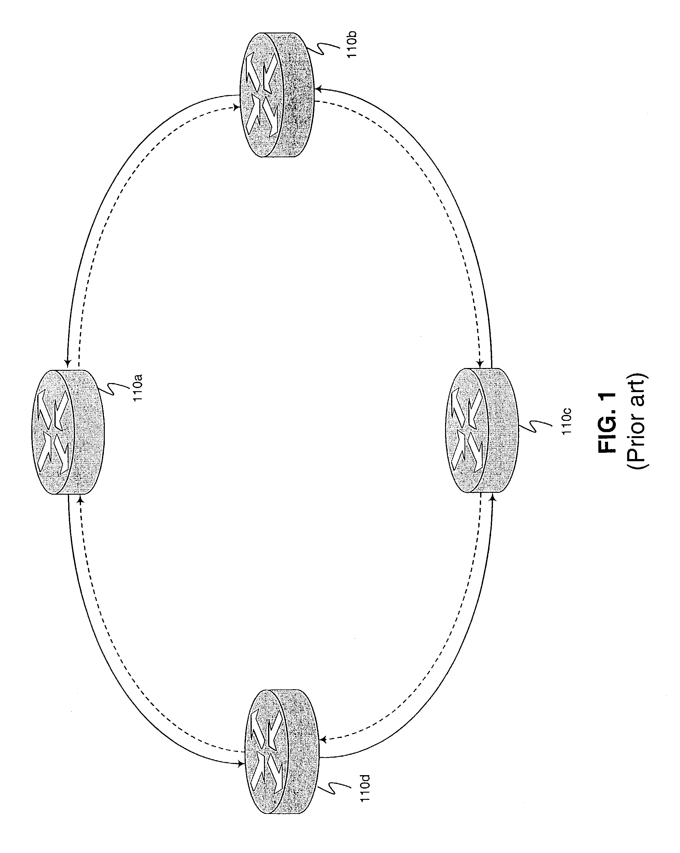
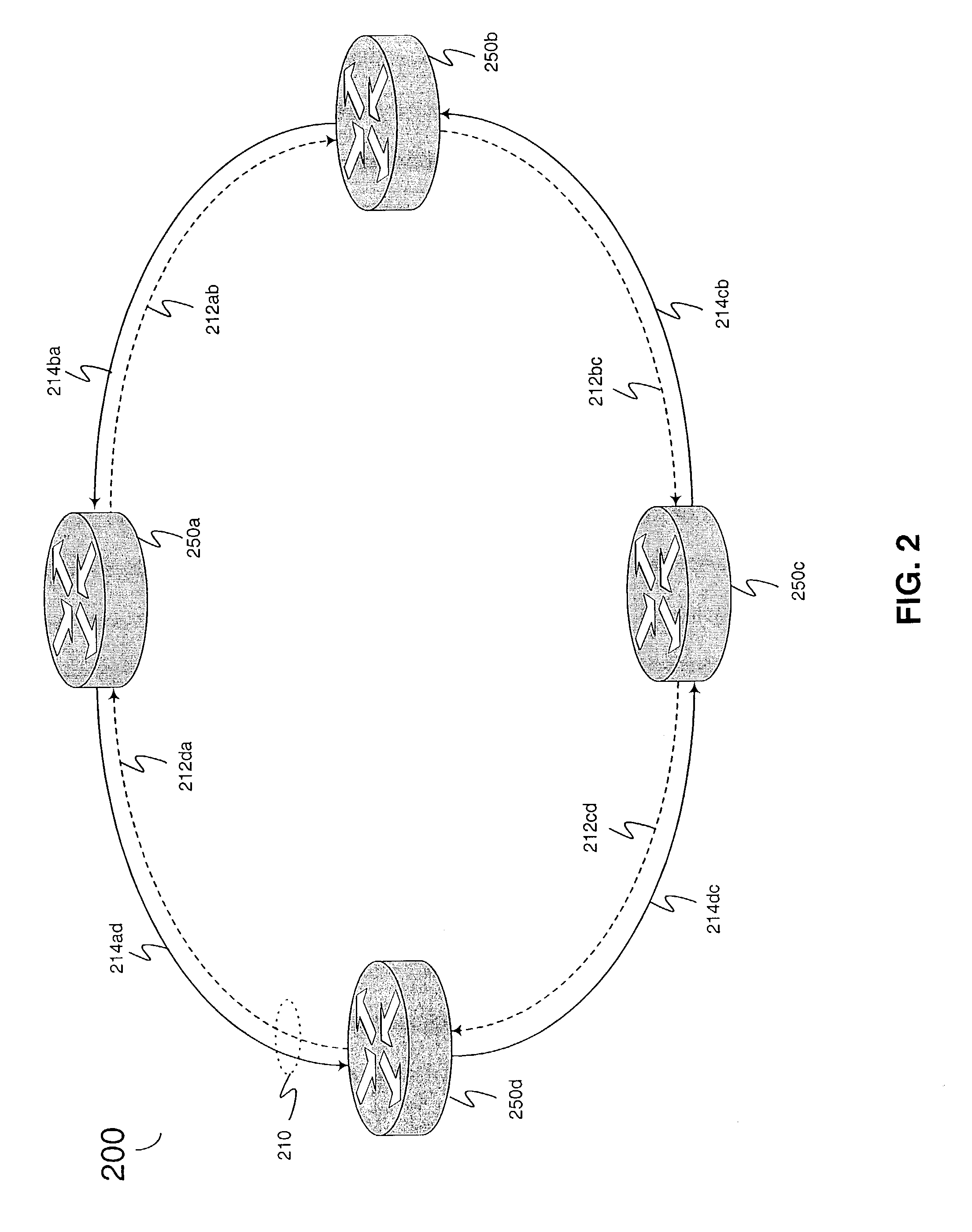
[0019]RPR or “Resilient Packet Ring” is a network architecture and technology for transmitting packet-based traffic. It provides features typically associated with SONET (efficient support for ring topology and fast recovery from fiber cuts and link failures) while at the same time, providing data efficiency, simplicity, and cost advantages that are typical to Ethernet. An example of an RPR network is described in the “IEEE 802.17 RPR Working Group Draft Standard v. 1.0,” which is incorporated by reference.

[0020]Generally described, RPR comprises a Media Access Control (MAC) data link layer protocol optimized for transmission on resilient rings used in local area networks (LANs), wide area networks (WANs), a...


PUM


Abstract

A method of allocating a plurality of traffic demands on a network having a plurality of stations connected by a bi-directional ring is disclosed. The method comprises selecting a first traffic demand from the plurality of traffic demands. The method then acquires a first existing traffic volume for a first direction of the bi-directional ring and a second existing traffic volume for a second direction of the bi-directional ring. Either the first or second direction is selected for transmitting the first traffic demand based on the smallest incremental increase in the load of the bi-directional ring.

Description

BACKGROUND OF THE INVENTION[0001]1. Field of the Invention[0002]The present invention relates generally to communication network management, and more particularly to a method and system for allocating traffic demands in full duplex, ring topology networks.[0003]2. Description of the Prior Art[0004]Traditional metropolitan networks have been designed for voice rather than data services using circuit-oriented technologies such as Synchronous Optical Networks (SONETs). Because SONET-based time-division multiplex (TDM) networks are typically deployed over fiber rings, much of the existing fiber plant in metropolitan areas is in ring form. Ring topologies enable SONET to implement a fast (e.g., sub 50 ms) protection mechanism that can restore connectivity using an alternate path around the ring in case of fiber cuts or equipment failure. The rapidly increasing demand for data traffic, however, is challenging the capacity limits of these existing transport infrastructures. This is compoun...

Claims


Application Information

Patent Timeline
Patent Type & Authority Patents(United States)
IPC IPC(8): G08C15/00
CPCH04L12/43H04L12/2852
Inventor KUBAT, PETERSMITH, JAMES MACGREGOR
Owner VERIZON PATENT & LICENSING INC
Why Eureka
Try Eureka