Low-cost electrostatic clamp with fast de-clamp time

a technology of electrostatic clamping and low-cost, which is applied in the direction of electrical equipment, semiconductor devices, and semiconductor/solid-state device details, etc. it can solve the problems of reducing the throughput of the wafer manufacturing process, jr clamps take much longer to de-clamp, typically 10 seconds or greater, and the backside of the wafer would suffer excessive particle contamination, etc., to achieve convenient use, convenient de-clamp, and the effect of reducing the throughput of the wa

Inactive Publication Date: 2010-05-11
AXCELIS TECHNOLOGIES
View PDF13 Cites 2 Cited by
  • Summary
  • Abstract
  • Description
  • Claims
  • Application Information

AI Technical Summary

Benefits of technology

[0013]Challenges of the prior art are overcome in the present invention by utilizing relatively inexpensive crystalline wafers in the manufacture of the electrostatic clamp. This represents substantial cost savings over existing manufacturing methods for electrostatic clamps. The invention exploits the well-known non-linear current transfer properties of a p-n diode to greatly reduce wafer de-clamping time. Starting with a ‘p’ type wafer or an ‘n’ type wafer, the wafer is doped in such a way that when the underlying electrode is energized with an applied voltage, for example, 800 V, the charge moves from the electrode up to the top surface of the “wafer material clamp”. With the charge at the upper surface of the wafer material clamp, it acts similar to current electrostatic clamps.
[0014]The present invention utilizes a relatively simple and inexpensive apparatus made of wafer material in comparison with various costly conventional electrostatic chucks. The invention takes advantage of the economies of scale that exist with commercially available semiconductor wafers, as well as the standardized precision and the material properties of wafers. The n- and p-layers can be tuned to achieve the desired current-voltage characteristics, for example, to improve the performance of the electrostatic clamp. The flatness of the dielectric is substantially similar to the flatness of the wafer, which is governed by SEMI standards and is extremely precise. Additionally, the thickness of the dielectric layer is extremely uniform, since it is governed by SEMI standards, as is the flatness for the wafer of the ESC. Lastly, the dielectric layer is of extremely high purity since it is also governed by the same standards mentioned above.
[0016]According to another aspect of the present invention, the p-n junctions can be tuned to achieve the desired current-voltage characteristics necessary for creating the desired electrostatic clamp. A bulk resistivity that is typically “seen” by the charge from the electrode to the outer clamping surface is on the order of about 109-1010 Ω−cm. This is a typical resistivity which is typically used, for example, in a JR type electrostatic clamp to efficiently allow the charge to migrate from the electrode to the surface of the ESC.
[0018]According to another aspect of the present invention, the electrostatic clamp can be built utilizing p-type wafers and n-type wafers combined with photolithographic processes to form the electrostatic clamp. In that way, the electrostatic clamp can take advantage of the superior properties, characteristics, etc., of the p-n junctions.
[0019]According to yet another exemplary aspect of the invention, the electrostatic clamp can be much less costly than current clamps. The wafers are readily available, of very high precision and relatively low cost for the current invention. In contrast, it is not uncommon for current electrostatic clamps to cost $35,000 or more. This is because of the flatness requirements, the necessary bulk resistivity of the ESC, the purity of the materials needed for the clamping, and the like. Whereas, a wafer utilized in manufacturing the clamp has a cost of approximately $300 or less and it exhibits the necessary flatness, thickness, material properties, etc., to work in an electrostatic clamp. Therefore, an electrostatic clamp utilizing silicon wafers can cost approximately $5,000 or less, which is equivalent to approximately an 85% reduction in cost, and yet have superior properties to existing clamps. In addition, the surface finish of a polished wafer is typically less than 1 nanometer (nm). This is much better than the surface finish of existing electrostatic clamps, typically 10 μm-50 μm. In addition, it can take over four months to build a conventional ESC. According to another exemplary aspect of the invention, there is a reduced production time for building the electrostatic clamps.

Problems solved by technology

In addition, it is critical that the wafer not slide on the clamp, as the clamping system would lose its frame of reference or index, and the backside of the wafer would suffer excessive particle contamination.
JR clamps can apply a force to the wafer that is much larger than a Coulombic clamp, for example, however, the JR clamps take much longer to de-clamp, typically 10 seconds or greater.
This wafer de-clamping problem can reduce the throughput of the wafer manufacturing process.
It is believed that the current wafer de-clamping problem occurs when residual charges induced by the clamping voltage remain on the dielectric layer or on a surface of the wafer, therein leading to undesirable residual electric fields and clamping forces.
This reversal voltage, however, is typically 1.5 to 2 times higher than the clamping voltage, and the de-clamping time is still typically quite large.
Such low-frequency sinusoidal AC voltages, however, typically provide low clamping forces, as well as fairly long residual clamping times.
In addition, the cost of manufacturing an ESC tends to be very high.
This is due in large part to the difficult manufacturing process involved in building an ESC.

Method used


Image

  • Low-cost electrostatic clamp with fast de-clamp time
  • Low-cost electrostatic clamp with fast de-clamp time
  • Low-cost electrostatic clamp with fast de-clamp time

Examples


Embodiment Construction

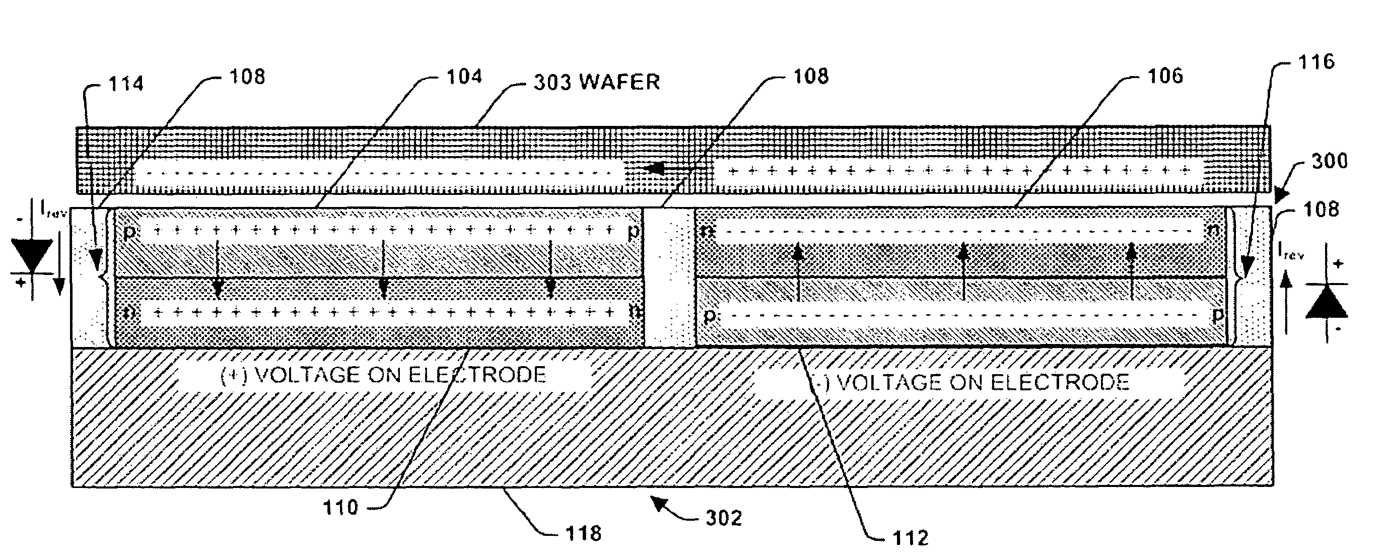
[0037]The present invention is directed towards a system and a method for clamping and de-clamping a wafer utilizing an electrostatic clamp (ESC) manufactured utilizing existing wafers. Accordingly, the present invention will now be described with reference to the drawings, wherein like reference numerals are used to refer to like elements throughout. It should be understood that the description of these aspects are merely illustrative and that they should not be taken in a limiting sense. In the following description, for purposes of explanation, numerous specific details are set forth in order to provide a thorough understanding of the present invention. It will be evident to one skilled in the art, however, that the present invention may be practiced without these specific details.

[0038]The present invention overcomes challenges of the prior art by providing a low cost and high precision system and method for clamping and de-clamping a wafer (e.g., a semiconductor substrate) and ...


PUM


Abstract

A method for manufacturing a semiconductor wafer electrostatic clamp, comprising providing a mounting plate, forming an insulative layer on an insulating portion of the mounting plate, forming a first electrode on a first portion of the mounting plate, forming a second electrode on a second portion of the mounting plate, forming a first segment having a first conductivity over the first electrode, forming a first region having a second conductivity over the first segment that creates an n-p type composite, forming a second segment having a third conductivity formed over the over the second electrode, forming a second region having a fourth conductivity formed over the second region that creates an p-n type composite.

Description

REFERENCE TO RELATED APPLICATION[0001]This application claims priority to and the benefit of U.S. Provisional Application Ser. No. 60 / 854,143 which was filed Oct. 25, 2006, entitled LOW-COST ELECTROSTATIC CLAMP WITH FAST DE-CLAMP TIME, the entirety of which is hereby incorporated by reference as if fully set forth herein.FIELD OF THE INVENTION[0002]The present invention relates generally to semiconductor electrostatic clamping systems and methods, and more specifically to a system and method for clamping a wafer / workpiece to an electrostatic chuck that utilizes “n” and / or “p” wafer segments, taken from a wafer(s), tuned to achieve specific and / or desired bulk resistivities.BACKGROUND OF THE INVENTION[0003]Electrostatic chucks (ESCs) have been utilized in plasma-based or vacuum-based semiconductor processes such as etching, CVD, ion implantation, and the like. A typical ESC, for example, comprises a dielectric layer positioned over a conductive electrode, wherein the semiconductor wa...

Claims


Application Information

Patent Timeline
Patent Type & Authority Patents(United States)
IPC IPC(8): H01L27/10
CPCH02N13/00H01L21/6833
Inventor LAFONTAINE, MARVIN RAYMONDPHARAND, MICHAELRUBIN, LEONARD MICHAELBECKER, KLAUS
Owner AXCELIS TECHNOLOGIES
Why Eureka
Try Eureka