User positioning

a positioning device and user technology, applied in the field of user positioning, can solve the problems of low use of positioning devices, poor measurement quality, and inability to use such technologies

Inactive Publication Date: 2010-05-11
WSOU INVESTMENTS LLC
View PDF17 Cites 17 Cited by
  • Summary
  • Abstract
  • Description
  • Claims
  • Application Information

AI Technical Summary

Benefits of technology

[0010]Therefore, the object underlying the invention resides in providing a low-cost method for positioning a user.

Problems solved by technology

In some cases, in fact, the number of Base Transceiver Stations (BTS's) in case of Uplink TOA / Enhanced OTD or satellites, in case of Network-Assisted GPS, that can be used for positioning purposes is low or the quality of the measurement is so poor that none of such technologies can be used.

Method used


Image

  • User positioning
  • User positioning
  • User positioning

Examples


first embodiment

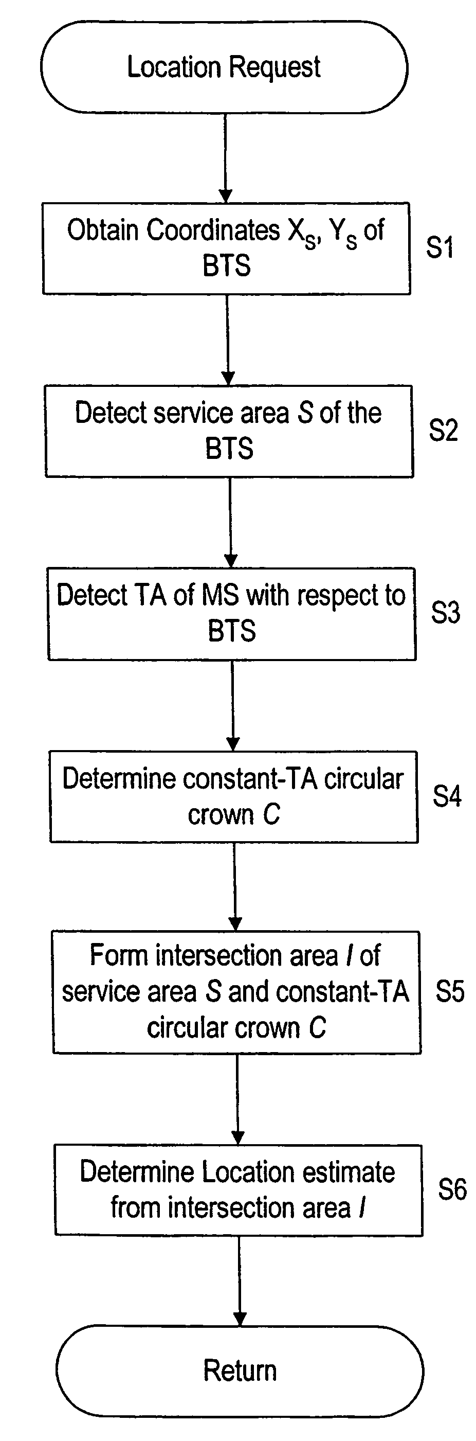
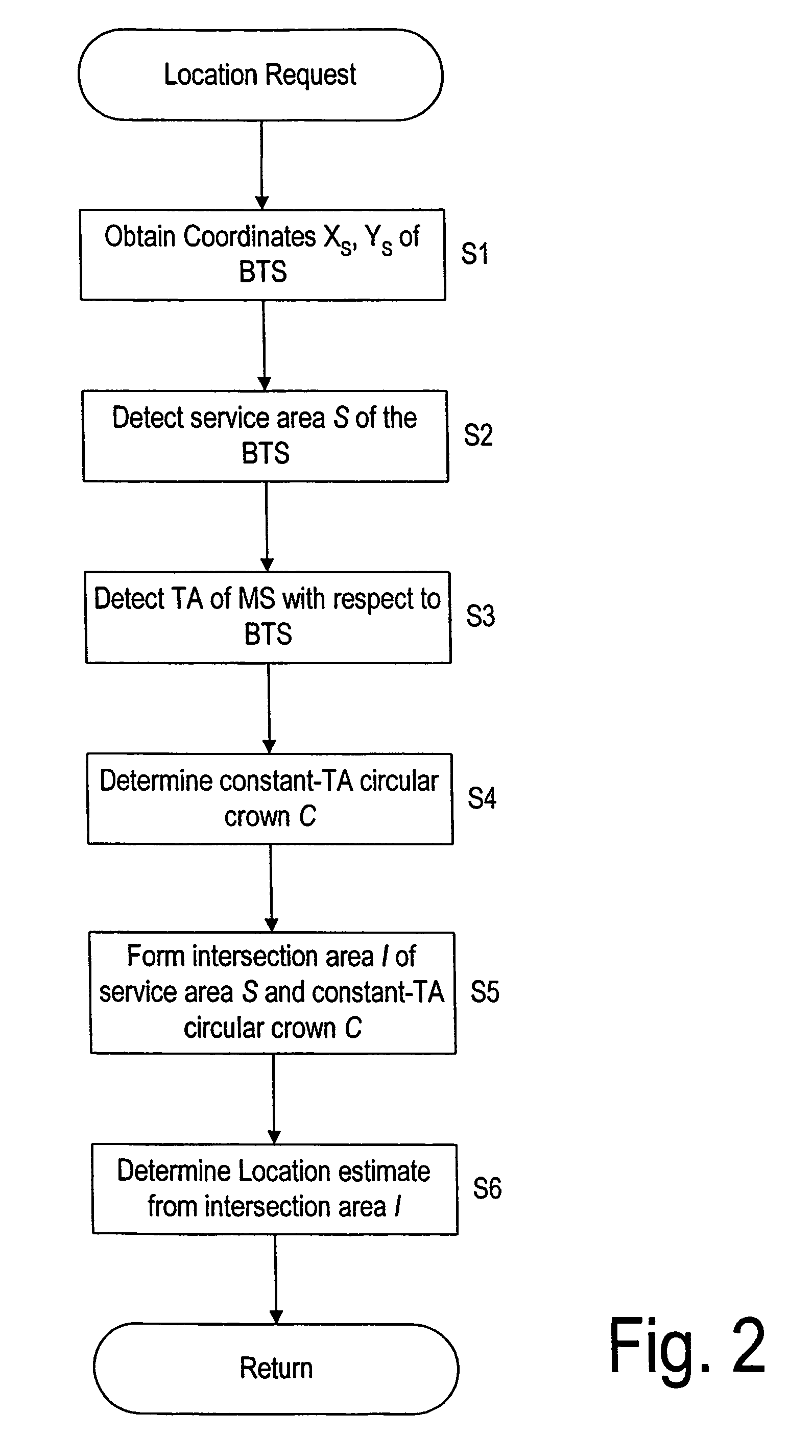
[0103]According to the first embodiment, an algorithm is used that extends the Timing Advance (TA) concept.

[0104]Namely, from the service deployment point of view, the Timing Advance procedure has a very high potential. Operators can start offering location services based on the Timing Advance system. Such services can be provided to all customers with reasonable additional costs (for both customers and operators). The introduction of services based on the Timing Advance procedure allows at the same time to build awareness and create needs of location-based services in the market. When a sufficient set of location-based services have been launched and the market demand for better location services exists, operators can start deploying more expensive location systems in their networks starting with the Enhanced OTD and continuing with the Assisted GPS.

[0105]The algorithm according to the first embodiment extends the Timing Advance (TA) concept by integrating the information available...

second embodiment

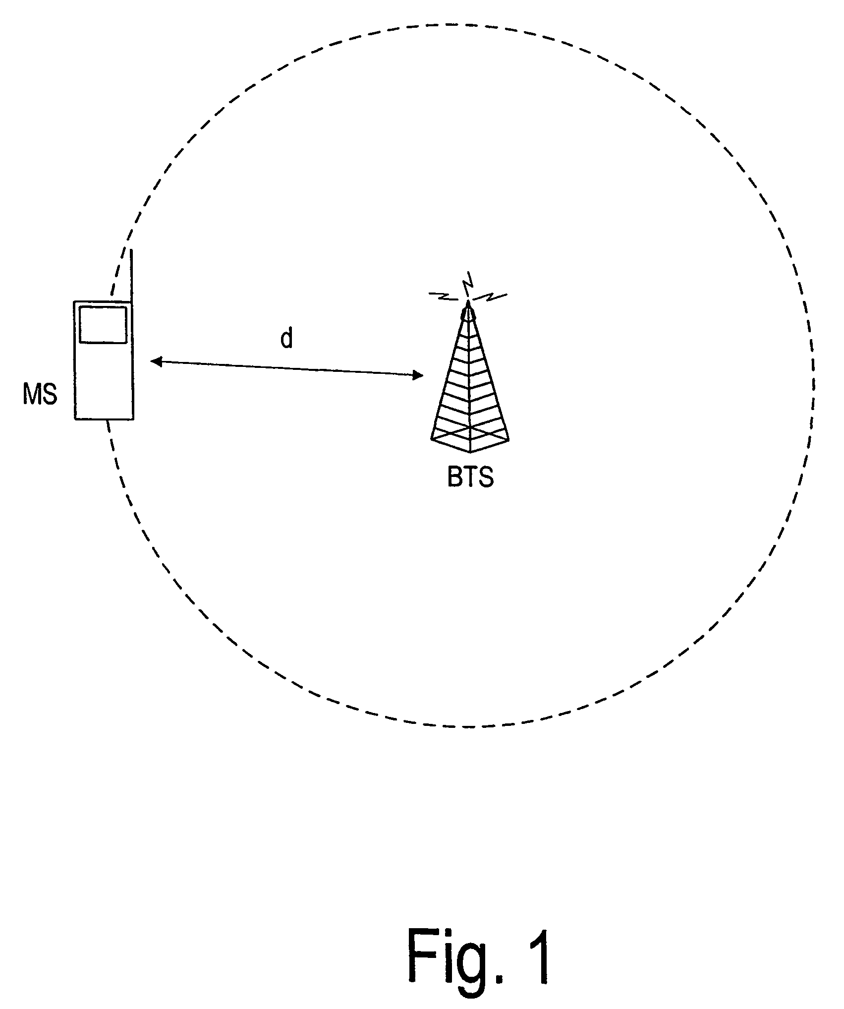
[0301]According to the first embodiment, the procedure to locate Mobile Stations (MS's) uses Cell Identity (CI), Timing Advance (TA), radio coverage data and statistical models for the TA measurement. The procedure according to the first embodiment uses only information related with the serving Base Transceiver Station (BTS).

[0302]However, according to the second embodiment described in the following, an extension of the procedure of the first embodiment is used, which includes in the location calculation the hearability area of neighbor BTS's measured by the MS to be located.

[0303]According to the first embodiment, the location algorithm is also implemented according to the VELOCITA (VEctorial LOcation with CI-TA) concept. The extension proposed in this embodiment can also be used in such implementation.

[0304]According to the second embodiment, the hearability area of the neighbor BTS's is in particular used. In this context, such areas designate the geographical locations where th...

third embodiment

[0344]In the following, a third embodiment is described in which Cell Identity (CI), Timing Advance (TA) and strength of received Signals with radio coverage information are used to locate mobile stations.

[0345]In the GSM system, the identity of the i-th neighbor BTS, NIi, used in the second embodiment can be obtained in practice from the pair of parameters BSIC (Base Station Identity Code)+BCCH Carrier included by the MS in the normal measurement reports (layer 3 messages) sent to the serving BTS.

[0346]Measurement reports include, among other information, also the signal strength (RXLEV) measured by the MS on the BCCH frequency of the neighbor BTS's. This information can be used to refine further the procedure according to the second embodiment, in the sense that the contribution of the neighbor cells in the location calculation can be extended to include, beside the identity of neighbor cells (i.e. hearability areas), also the actual strength of signals measured by the MS.

[0347]Th...


PUM


Abstract

The invention proposes a method for locating a network element, comprising the steps of obtaining (S1) the coordinates (xS, yS) of a second network element (BTS) to which the first network element (MS) is connected or attached; detecting (S2) a serving area (S), which is served by the second network element (BTS); detecting (S3) a propagation delay of the first network element with respect to the second network element (BTS); determining (S4) a propagation delay depending area (C), which is an area having a distance to the second network element (BTS) based on the propagation delay and a width based on the propagation delay; and forming (S5) an intersection area (I) of the serving area (S) and the propagation delay depending area (C); wherein a location estimate of the first network element (MS) is determined (S6) from the intersection area (I). Thus, an uncertainty area where a first network element is located can be reduced and the location accuracy can be improved.

Description

FIELD OF THE INVENTION[0001]The present invention relates to a method and a network control device for locating a network element and, thus, for locating a user of such a network element.BACKGROUND OF THE INVENTION[0002]The need for an efficient and accurate user positioning in wireless networks grows day by day. The position estimation of wireless callers to emergency numbers, as the “Enhanced-911” (E-911) mandatory in the U.S. by October 2001 and the E-112 under consideration by the European Community, is only one of the possible applications beside vehicle fleet management, intelligent transport systems (ITS's) and location-based billing.[0003]To guarantee positioning in the whole coverage area, achieve different service requirements and handle the variety of location information, combinations of different location technologies have been considered and suitable signaling protocols proposed. Standardization of Mobile Stations (MS's) positioning in GSM networks started in 1995 with...

Claims


Application Information

Patent Timeline
Patent Type & Authority Patents(United States)
IPC IPC(8): H04W24/00H04W64/00
CPCH04W64/00
Inventor SPIRITO, MAURIZIORUUTU, VILLE
Owner WSOU INVESTMENTS LLC
Why Eureka
Try Eureka