Method for determining the rotational velocity of an axle and detecting a locked axle condition

a technology of rotational velocity and axle, which is applied in the direction of electric controllers, instruments, dynamo-electric converter control, etc., can solve the problems of affecting the handling characteristics of locomotives, affecting the speed of motor/axle, and affecting the operation efficiency of locomotives, etc., to achieve the effect of reliable determination of the speed of the motor/axl

Inactive Publication Date: 2011-03-29
GE GLOBAL SOURCING LLC
View PDF15 Cites 9 Cited by
  • Summary
  • Abstract
  • Description
  • Claims
  • Application Information

AI Technical Summary

Benefits of technology

[0009]Therefore, there is a need for a low-cost method to reliably determine the speed of the motor / axle and to thus determine when a locked axle condition occurs in a vehicle wherein the excitation source is not available or is otherwise not desirable for use and wherein the method does not rely solely on axle speed sensors for locked axle detection.

Problems solved by technology

This locked axle condition will cause the axle wheel to slide along the rail and could adversely affect the handling characteristics of the locomotive.
Unfortunately, this method has a number of disadvantages.
One disadvantage is that stopping locomotives, inspecting axles and operating at slower speeds involve burdensome delays and can be expensive.
A second disadvantage of this method is that it allows a large amount of electric power to be lost when an axle becomes locked.
When an axle becomes locked power is still supplied by the locomotive to drive the traction motor and this power becomes lost in the semiconductor devices of the traction motor.
A third disadvantage is that if any of the electronic components of the locked axle speed sensor and / or speed detection system fails then locked axle detection is not possible.
Similarly if the speed sensor connected to the speedometer is not functional, the locomotive may not operational due to potential inability to be operated within the speed limit.
Moreover, the application of power to the motor produces losses in the power semiconductor devices and other electrical components, such as the motor and alternator.
These speed sensors, while adequate for their intended purposes, can be costly and may experience failures.
Therefore, additional speed sensors for redundancy may not be desirable.
However there are many operating conditions of a locomotive when an excitation voltage is not available.
For example, when the engine is not running, or when the locomotive is in isolated mode such that the alternator cannot produce voltage.
Another instance when an excitation voltage is not available is when there is a failure or unavailability of the components used in the production of AC voltage to the motor like inverters and power electronics.
Furthermore, a failure in the components used to produce voltage to the inverter like the alternator and its field excitation system or failure in the components attached to the DC traction bus (like dynamic brake grid resistors and contactors or failure in the diesel engine components).

Method used


Image

  • Method for determining the rotational velocity of an axle and detecting a locked axle condition
  • Method for determining the rotational velocity of an axle and detecting a locked axle condition
  • Method for determining the rotational velocity of an axle and detecting a locked axle condition

Examples


Embodiment Construction

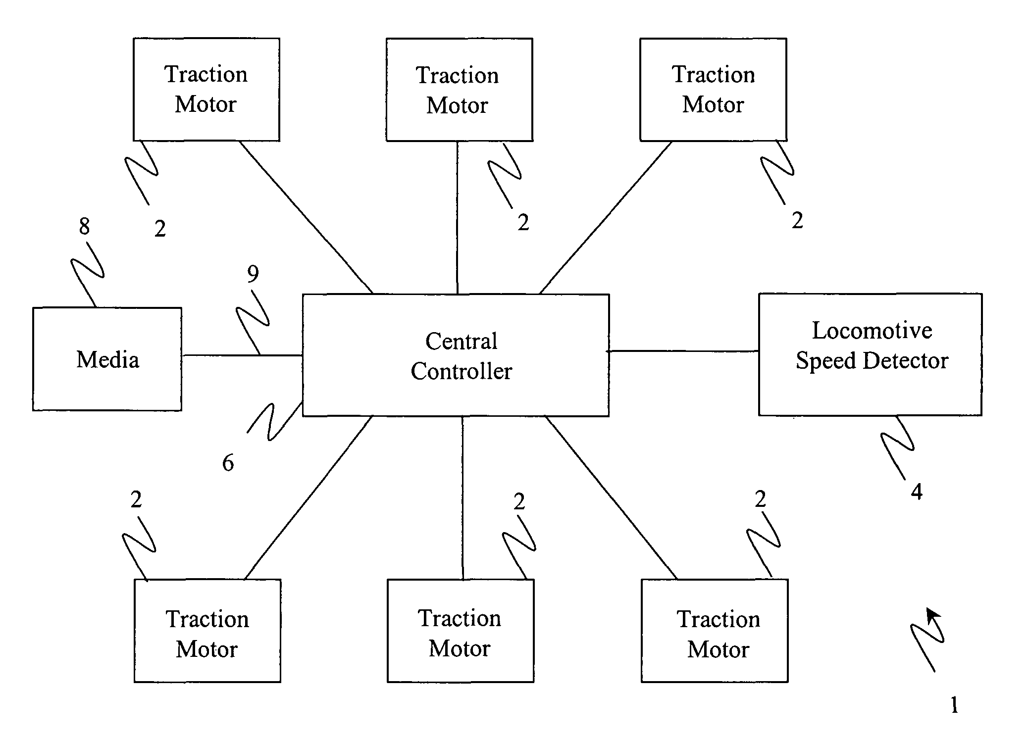
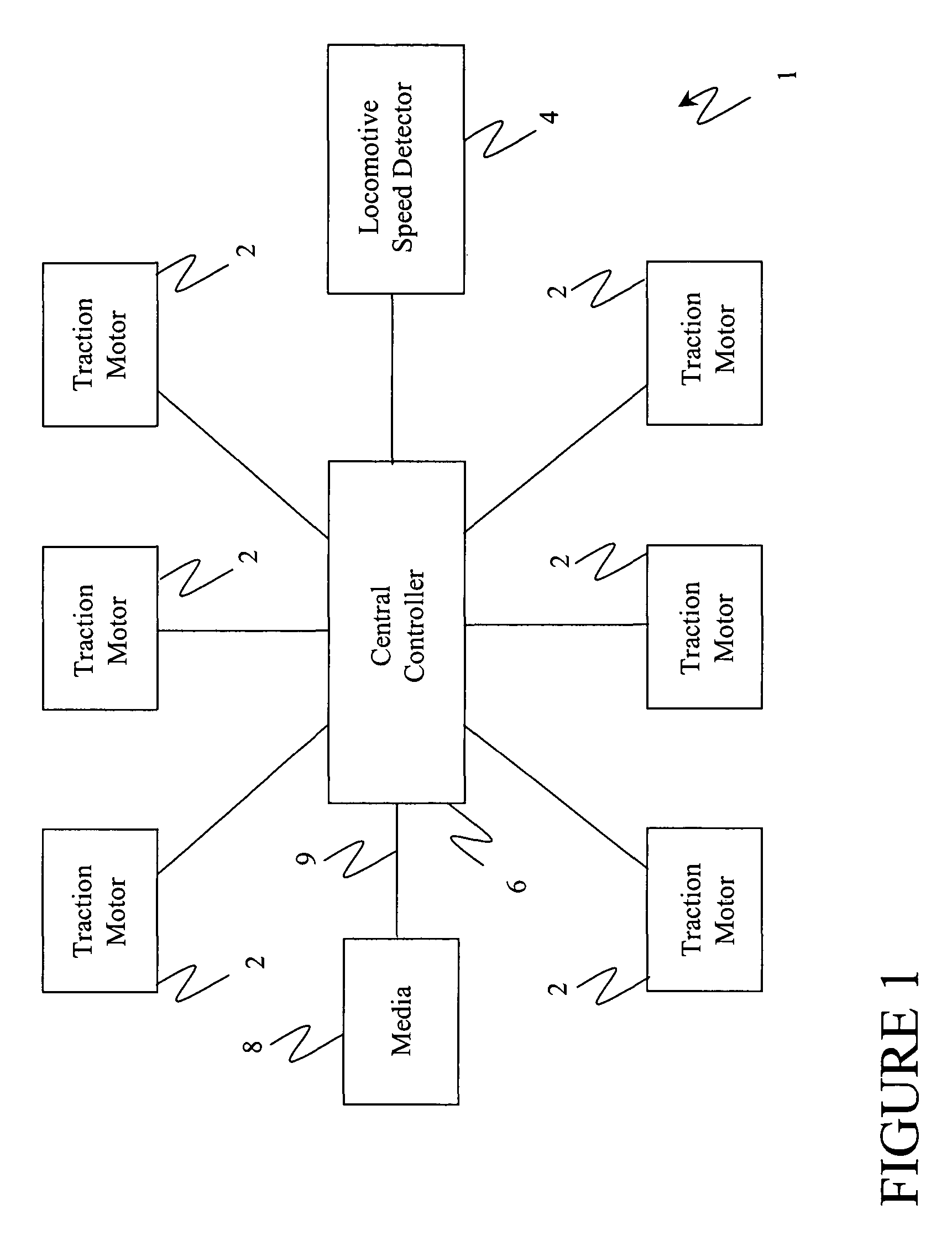
[0026]It should be noted that although an exemplary embodiment is illustrated hereinafter with regard to a locomotive, it is considered within the scope this embodiment that the method may be applied to any vehicle 1 or device having a motor which produces a back electromotive force (EMF).

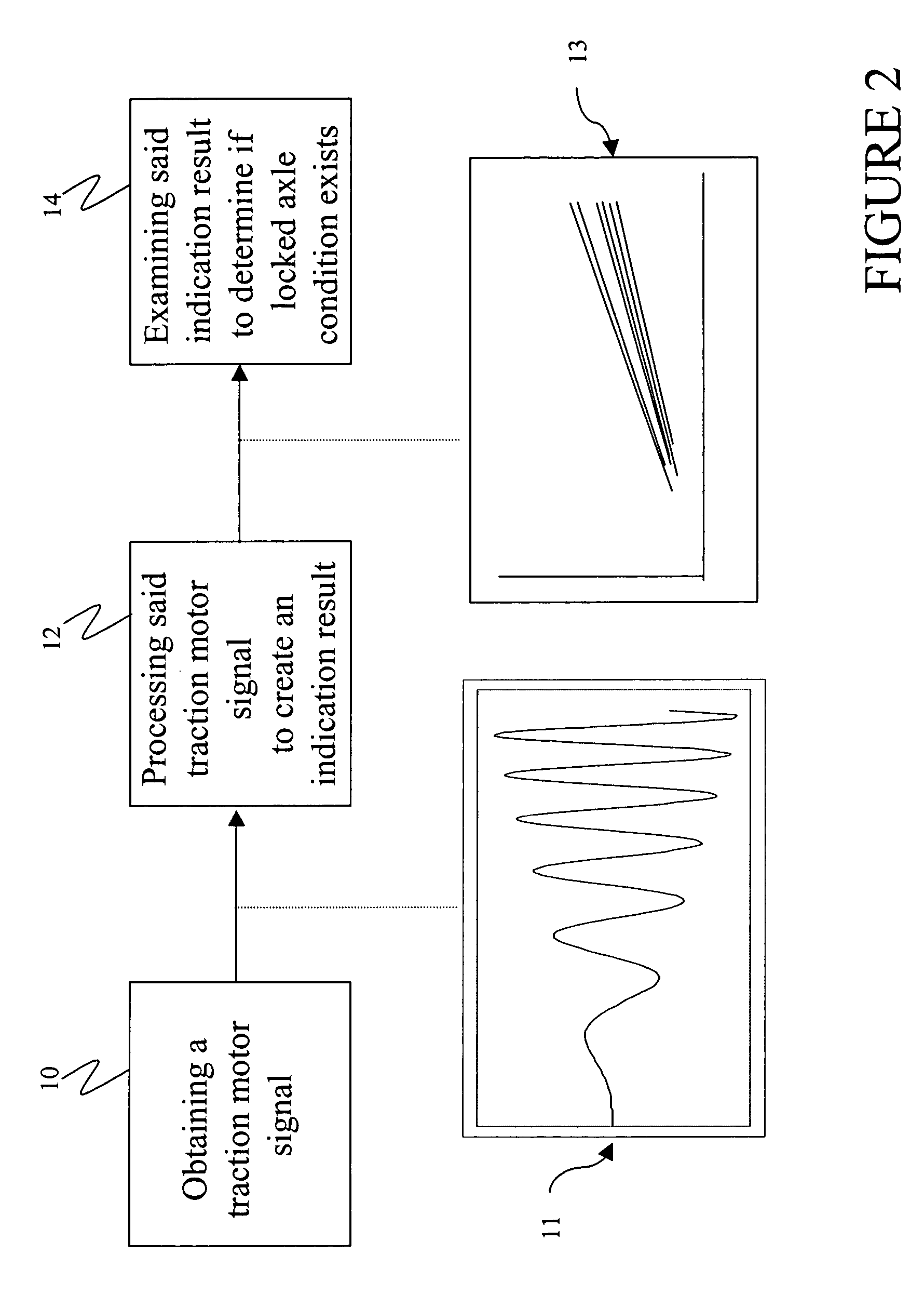
[0027]When turning, AC traction motors produce a small AC voltage (back EMF or electro motive force) across their terminals due to a residual magnetic flux. The amplitude of this voltage depends on the residual flux in the machine and the residual flux itself depends upon the motor characteristics and its operational history. The frequency of this induced voltage is proportional to the speed of the motor. An exemplary embodiment of the invention makes use of this back EMF voltage produced during non-excited state of the traction motor operation to determine a rotational velocity of the motor and optionally whether a locked axle condition exists. Therefore, a technical effect of an exemplary embodim...


PUM


Abstract

A method for detecting a rotational velocity of a traction motor in a vehicle comprising: obtaining a traction motor signal having at least one phase, wherein the traction motor signal is responsive to an operating condition of the traction motor in an electrically unexcited state. The method also includes processing the traction motor signal to create an indication result based on a frequency of the traction motor signal and determining rotational velocity of the traction motor based on the indication result.

Description

CROSS-REFERENCE TO RELATED APPLICATIONS[0001]This application is a continuation-in-part application of U.S. Ser. No. 10 / 066,233, filed Jan. 31, 2002 now U.S. Pat. No. 6,728,606 the contents of which are incorporated by reference herein in their entirety.BACKGROUND OF THE INVENTION[0002]This invention relates generally to a method for determining the rotational velocity of an axle (and in the limiting case of no detected axle speed then to also serve to detect a locked axle condition for a vehicle). More particularly, the invention relates to a method for determining the rotational velocity of an axle and detecting a locked axle condition for an AC locomotive, which is propelled by AC traction motors.[0003]Locomotives used for hauling applications are generally equipped with speed sensors coupled to individual traction motors or to the axles driven by the traction motors. The speed sensor data or speed sensor information is monitored and is used for various function like torque produ...

Claims


Application Information

Patent Timeline
Patent Type & Authority Patents(United States)
IPC IPC(8): G05D1/00H02P1/54B60T8/17
CPCB60T8/1705
Inventor KUMAR, AJITH KUTTANNAIR
Owner GE GLOBAL SOURCING LLC
Why Eureka
Try Eureka