
EGR detection via humidity detection

a technology of exhaust gas recirculation and humidity detection, which is applied in the direction of electrical control, process and machine control, instruments, etc., can solve the problems of increased emissions and decreased engine driveability, fluctuation of air-fuel ratio, and engine performance degradation, and achieve the effect of egr

Inactive Publication Date: 2010-05-11
FORD GLOBAL TECH LLC
View PDF19 Cites 107 Cited by
  • Summary
  • Abstract
  • Description
  • Claims
  • Application Information

AI Technical Summary

Benefits of technology

[0003]One example approach for determining an amount of EGR is described in U.S. Pat. No. 5,145,566. In this example, EGR flow is determined based on humidity during conditions in which the engine is operating with a stoichiometric air-fuel ratio. Specifically, an exhaust gas sensor is employed to measure a relative amount of water vapor in an exhaust gas / intake air mixture as a relative amount of water in the exhaust gas / intake air mixture is dependent on the relative amount of EGR. Additionally, a second sensor is employed to determine a relative amount of water vapor in the air surrounding the vehicle (e.g., ambient water vapor). In this way, the amount of EGR may be accurately determined by adjusting the first measurement based on the relative amount of ambient water vapor.

Problems solved by technology

Although EGR may be beneficial, an inaccurate determination of the amount of EGR may be detrimental to overall engine performance, resulting in increased emissions and decreased engine driveability.
During engine operation, however, the air-fuel ratio may fluctuate from stoichiometry (e.g., it may become lean or rich).
As such, the above method may produce an erroneous estimate of the amount of exhaust gas recirculation resulting in degraded engine performance including a loss of power and increased emissions.
Further, the above method assumes a fuel of 100% gasoline and does not account for varying amounts of alcohol in the fuel (e.g., E85, which is 85% ethanol and 15% gasoline).
Fuel blends comprising varying amounts of alcohol also affect the products of combustion which may lead to an inaccurate determination of exhaust gas recirculation when utilized by the above approach.

Method used


Image

  • EGR detection via humidity detection
  • EGR detection via humidity detection
  • EGR detection via humidity detection

Examples


Embodiment Construction

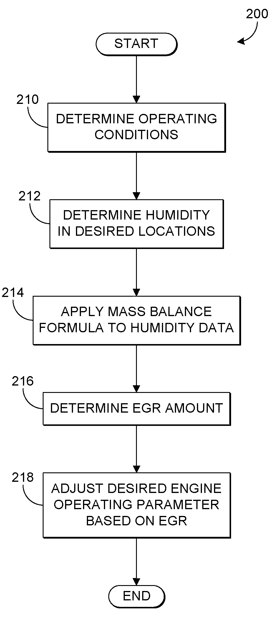
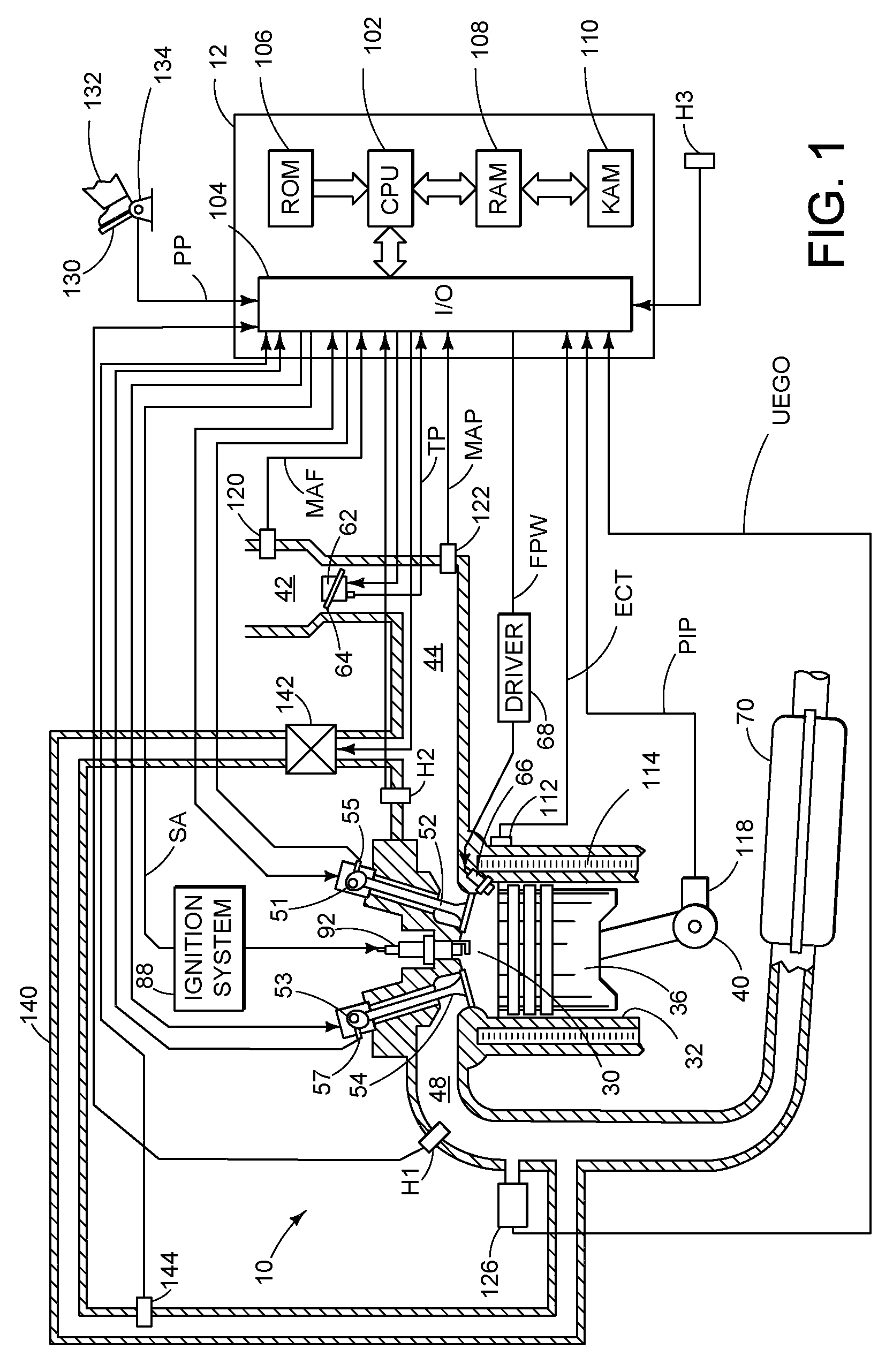
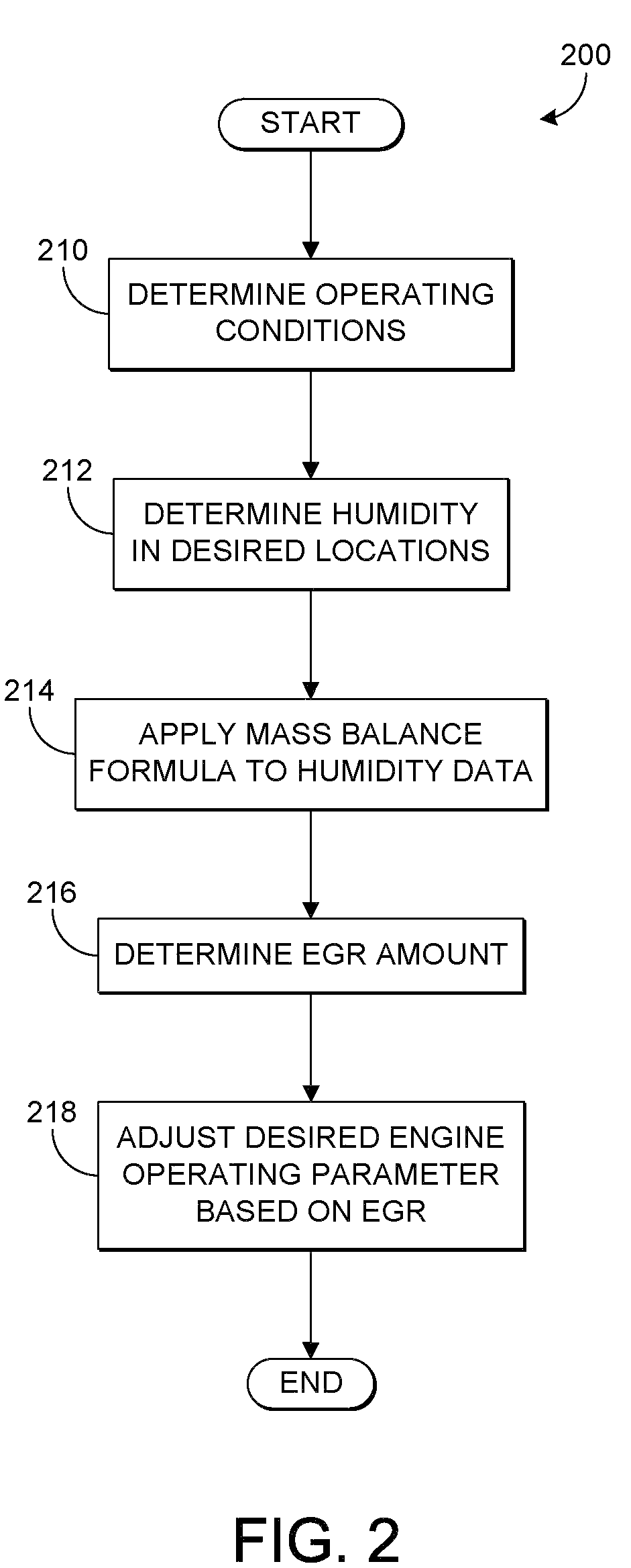
[0012]The following description relates to a method for operating an engine in a motor vehicle wherein an engine control system is configured to adjust engine operating parameters in response to an amount of exhaust gas recirculation (EGR). An amount of EGR may be determined based on a plurality of humidity readings generated in a plurality of locations, with at least a first humidity sensor being located in an intake manifold and a second humidity sensor being located in an exhaust manifold. In such a configuration, indications of the water vapor concentration in the intake manifold and the exhaust manifold, as well as an ambient water vapor concentration, may be generated. The plurality of generated humidity indications may be utilized in a mass balance formula that may be applied to the intake air (a combination of ambient air and exhaust gas from the EGR system) in order to determine an accurate amount of EGR. Consequently, because a humidity sensor located in the exhaust manifo...


PUM


Abstract

Various systems and methods are described for controlling an engine in a vehicle which includes an exhaust passage and an exhaust gas recirculation system. One example method comprises adjusting an engine operating parameter based on an exhaust gas recirculation amount, the exhaust gas recirculation amount based on a first humidity and a second humidity, the first humidity generated from a first humidity sensor at a first location and the second humidity generated from a second humidity sensor located in the exhaust passage of the engine.

Description

TECHNICAL FIELD[0001]The present application relates to an exhaust gas recirculation (EGR) system for an engine in a motor vehicle.BACKGROUND AND SUMMARY[0002]Internal combustion engines may utilize exhaust gas recirculation (EGR) in order to reduce emissions such as nitrogen oxides (NOx). Although EGR may be beneficial, an inaccurate determination of the amount of EGR may be detrimental to overall engine performance, resulting in increased emissions and decreased engine driveability.[0003]One example approach for determining an amount of EGR is described in U.S. Pat. No. 5,145,566. In this example, EGR flow is determined based on humidity during conditions in which the engine is operating with a stoichiometric air-fuel ratio. Specifically, an exhaust gas sensor is employed to measure a relative amount of water vapor in an exhaust gas / intake air mixture as a relative amount of water in the exhaust gas / intake air mixture is dependent on the relative amount of EGR. Additionally, a sec...

Claims


Application Information

Patent Timeline
IPC IPC(8): F02M25/07F02B47/10
CPCF02M25/0755F02D41/0072F02B47/10F02D13/0207F02D13/0219Y02T10/47F02D2200/0418F02M25/0754F02M26/46F02M26/47Y02T10/40
Inventor XIAO, NIANKERNS, JAMES MICHAELDING, YI
Owner FORD GLOBAL TECH LLC
Learn More