Method for identifying and removing multiples for imaging with beams

a beam and multiple technology, applied in the field of seismic exploration and processing, can solve the problems of severe masking of primary reflection events for structural imaging, no useful information in multiples, and inability to accurately predict multiples

Active Publication Date: 2010-05-11
CHEVROU USA INC
View PDF9 Cites 44 Cited by
  • Summary
  • Abstract
  • Description
  • Claims
  • Application Information

AI Technical Summary

Problems solved by technology

One prevalent issue with the seismic energy recorded by the receivers during the data acquisition stage is that the seismic traces often contain both the desired seismic reflections (the “primary” reflections) and unwanted multiple reflections which can obscure or overwhelm the primary seismic reflections.
In most cases, multiples do not contain any useful information that is not more easily extracted from primaries.
Moreover, water-bottom multiples have been recognized as the most serious noise problem in seismic data processing in many offshore areas.
Multiples can severely mask primary reflection events for structural imaging and contaminate Amplitude vs.
Other model-driven methodologies require the shape of the source wavelet that will not be a pure delta function because of the reverberations and frequency bandwidth limitation.
However, these methods do require one shot location for each receiver position, and this is not the case for most three dimensional (“3D”) acquisition geometries.
SRME methodologies are generally challenged by complex 3D multiples because of large shot spacing, narrow spread length and / or wide cable spacing.
The missing data can be interpolated or extrapolated from the existing data, but interpolation of extrapolation has trouble with aliased seismic data caused by the large shot and / or receiver spacing.
Advanced interpolation or extrapolation methods can also be difficult to implement and expensive.
A common cause of these complex 3D data that challenge 3D SRME methods is rugosity on the top of salt.
But, any type of complex overburden can cause complex 3D seismic data that is hard to interpolate.
In addition, predictive deconvolution often leads to inadvertent damage to the primaries due to the difficulty in separating the multiples and primaries.
Moreover, predictive deconvolution often fails to take into account the nonlinear factor in the reflectivity, which are generally caused by peg-leg multiples.

Method used


Image

  • Method for identifying and removing multiples for imaging with beams
  • Method for identifying and removing multiples for imaging with beams
  • Method for identifying and removing multiples for imaging with beams

Examples


Embodiment Construction

[0045]While this invention is susceptible to embodiments in many different forms, there are shown in the drawings, and will herein be described in detail, preferred embodiments of the invention with the understanding, that the present disclosure is to be considered as an exemplification of the principles of the invention and is not intended to limit the broad aspect of the invention to the embodiments illustrated.

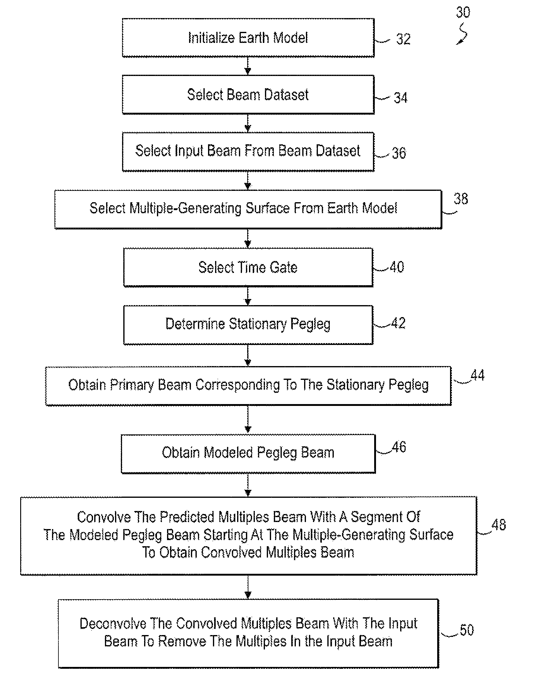
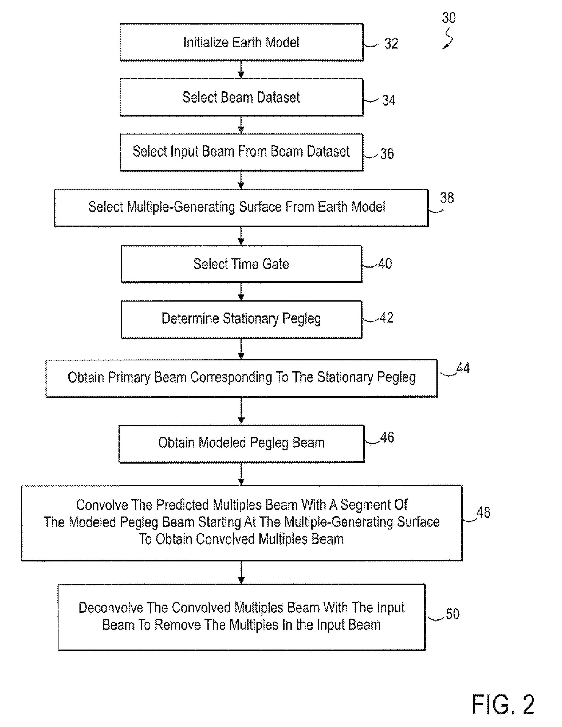
[0046]One embodiment of the present invention 30 is illustrated in FIG. 2. The embodiment includes initializing an earth model that corresponds to a geological area of interest 32 and selecting a beam dataset derived from seismic data collected in the geological area of interest 34. An input beam from the beam dataset 36, a multiple-generating surface from the earth model 38, and a time gate 40 are selected. A stationary pegleg is determined utilizing the input beam, the multiple generating surface and the time gate 42. A primary beam corresponding to the stationary pegleg ...


PUM


Abstract

The present invention incorporates the use of model-driven and data-driven methodologies to attenuate multiples in seismic data utilizing a prediction model which includes multiply-reflected, surface-related seismic waves. The present invention includes beam techniques and convolving a predicted multiples beam with a segment of a modeled pegleg beam to obtain a convolved multiples beam. The convolved multiples beam can then he deconvolved to attenuate the multiples that are present in the original input beam.

Description

BACKGROUND OF THE INVENTION[0001]This invention relates to seismic exploration and processing, and more specifically to imaging with beams and a method to predict multiples based on primaries by combining both model-driven and data-driven methodologies.[0002]In the petroleum industry, seismic prospecting techniques are commonly used to aid in the search for and the evaluation of subterranean hydrocarbon deposits. In seismic prospecting, one or more sources of seismic energy emit waves into a subsurface region of interest such as a geologic formation. These waves enter the formation and may be scattered, e.g., by reflection or refraction, by subsurface seismic reflectors (i.e., interfaces between underground formations having different elastic properties). The reflected signals are sampled or measured by one or more receivers, and the resultant data are recorded. The recorded samples may be referred to as seismic data or a set of “seismic traces”. The seismic data may be analyzed to ...

Claims


Application Information

Patent Timeline
Patent Type & Authority Patents(United States)
IPC IPC(8): G01V1/00G01V1/28G01V1/38
CPCG01V1/364G01V2210/56
Inventor NEMETH, TAMASWANG, YUEQIN, FUHAOHILL, ROSS
Owner CHEVROU USA INC
Why Eureka
Try Eureka