Method and instrumentation for posterior interbody fusion

a technology of interbody fusion and instrumentation, applied in the field of surgical procedures for spinal stabilization, can solve the problems of inability to provide adequate protection for the sensitive vessels and neurological structures, and inability to further improve the method

Inactive Publication Date: 2010-05-25
WARSAW ORTHOPEDIC INC
View PDF63 Cites 51 Cited by
  • Summary
  • Abstract
  • Description
  • Claims
  • Application Information

AI Technical Summary

Benefits of technology

[0007]One object of the present invention is to provide an improved retractor assembly permitting variable placement of the handle with respect to a retractor blade. The retractor comprises a retractor blade, a shaft having a first portion connected to the retractor blade, and an opposite second portion pivotally connected to a handle. Preferably, the assembly further includes a locking mechanism selectively locking the handle to the second portion to limit pivotal movement of the handle in relation to the shaft.

Problems solved by technology

Thus, Cloward's method and instrumentation was designed for and limited to an anterior surgical approach and was inappropriate for a posterior application.
While Wilterberger had taken the Cloward concept of circular drilling followed by dowel fusion and applied it to the lumbar spine from a posterior approach, he had not further improved the method, nor had he advanced the instrumentation to provide adequate protection for the sensitive vessels and neurological structures adjacent to the operating field.

Method used


Image

  • Method and instrumentation for posterior interbody fusion
  • Method and instrumentation for posterior interbody fusion
  • Method and instrumentation for posterior interbody fusion

Examples


second embodiment

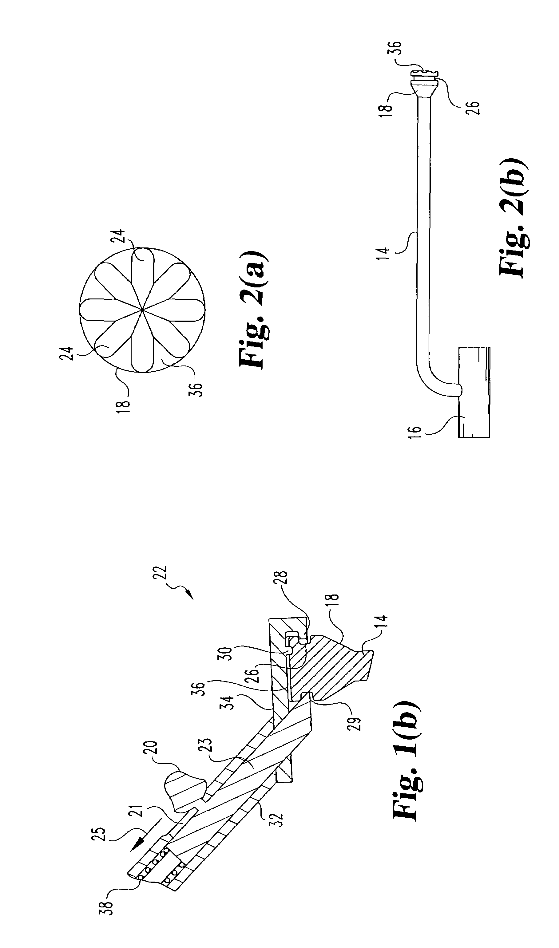
[0055]Referring now to FIG. 5, there is disclosed an intraoperative template according to the present invention. A second template 52 includes a handle 54 connected to a shaft 56 which is centrally connected to template body 58. Template body 58 further includes guide tube 60 and integrally formed post 62. A trephine 64 is illustrated extending into and through guide tube 60 with trephine cutting head 66 extending beyond distal end 61 of guide tube 60. The addition of post 62 to the template permits a surgeon to straddle the dura and place post 62 to further assist in the alignment of any further trephining procedures.

[0056]Referring now to FIG. 10, template body 48 includes six indentations 50 along the perimeter of the device. The perimeter of the device matches the amount of exposure required for placement of a pair of implants. Preferably, the body is sized to match the space needed to place two cylindrical bone dowels. Therefore, if in placing template body 48, bony structures ...

first embodiment

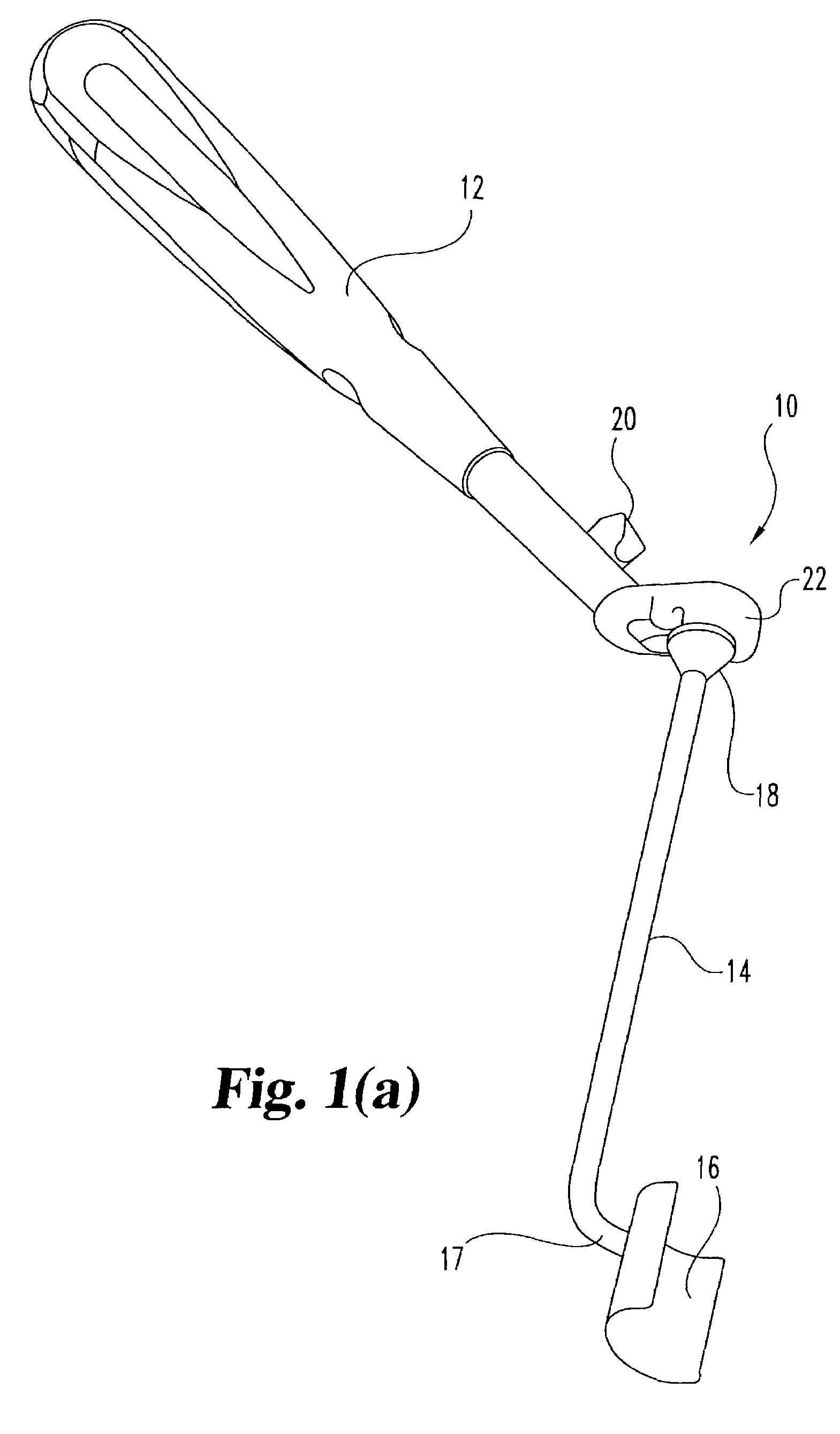
[0067]In a first embodiment shown in FIG. 19(a), collar 302 is retained on housing 306 by retaining pin 322 extending into the housing and through a slot 320. Retaining pin 322 prevents rotation of collar 232 with respect to housing 318. In an alternate embodiment shown in FIG. 24, collar 302 defines an L-shaped slot 324 which permits axial displacement of collar 302 with respect to body 318, as well as a slight amount of rotation within the slot. It will be understood that the L-shaped slot 324 permits the depth stop mechanism to be locked in a disengaged position which permits free movement of a tool shaft through the depth stop. This is a desirable construction in some instances for easy removal of the depth stop from the tool shaft, as well as for utilization of the tool without the constraints of a depth stop mechanism.

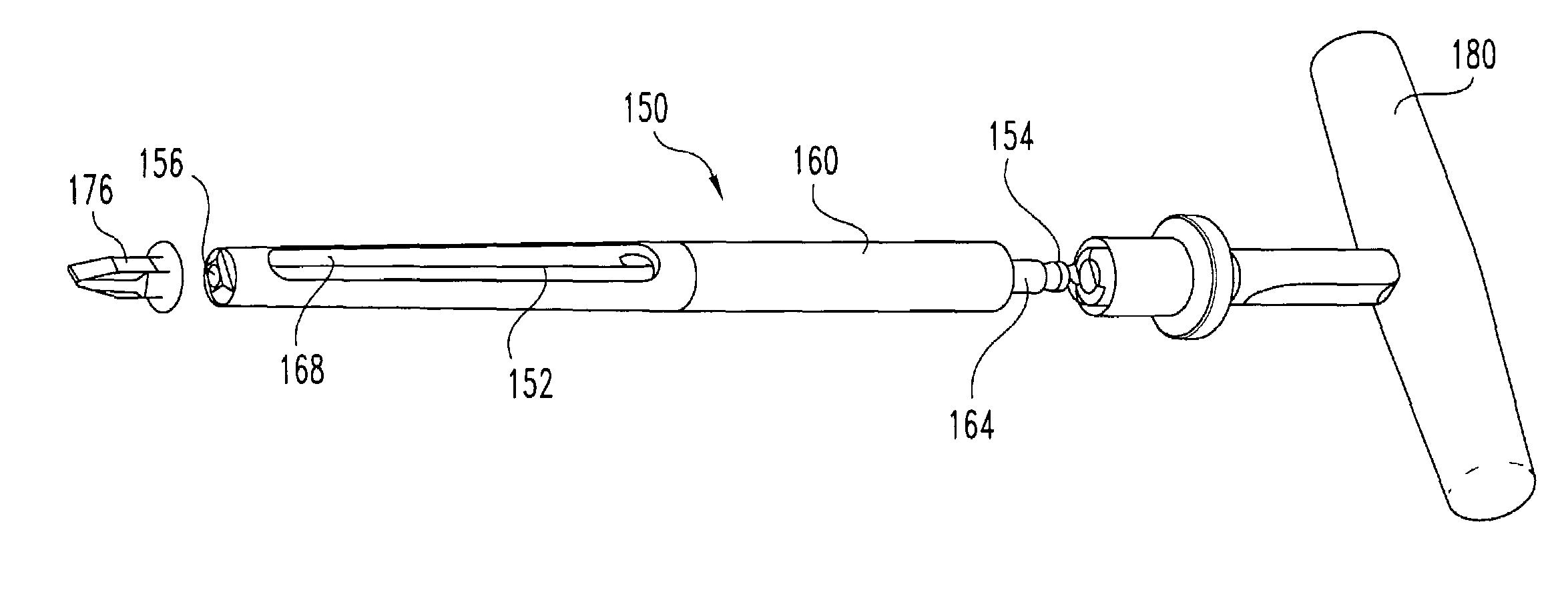
[0068]Referring now to FIG. 21, there is shown an outer sleeve 210 in combination with a depth stop 300 and reamer 351. The reamer 351 is interconnected with a T...


PUM


Abstract

A method and instrumentation for spinal interbody fusion is disclosed. The instruments and methods are particularly adapted for interbody fusion from a posterior approach to the spine. One instrument is a retractor having a lockable pivotally mounted handle. Another instrument is a template for straddling the dura. A modular distractor is also provided and preferably includes a tapered shaft with a visualization window disposed therein. Yet another instrument is a depth gauge to verify bone opening depth and dimension, preferably including a radiopaque portion. A method contemplates the use of these instruments to prepare a disc space to receive an implant.

Description

REFERENCE TO RELATED APPLICATIONS[0001]This application is a divisional application of U.S. patent application Ser. No. 09 / 829,655 filed on Apr. 10, 2001 now U.S. Pat. No. 6,506,151 which is a divisional application of U.S. patent application Ser. No. 09 / 179,799 filed on Oct. 27, 1998, now U.S. Pat. No. 6,241,729, which claims the benefit of U.S. Provisional Application No. 60 / 081,206 filed Apr. 9, 1998, the contents of each application hereby being incorporated by reference.BACKGROUND OF THE INVENTION[0002]The present invention relates generally to surgical procedures for spinal stabilization and more specifically to instrumentation and techniques for inserting a spinal implant within the intervertebral disc space between adjacent vertebra. More particularly, while aspects of the present invention may have other applications, the invention provides instruments and techniques especially suited for interbody fusion from a generally posterior approach to the spine[0003]Various surgica...

Claims


Application Information

Patent Timeline
Patent Type & Authority Patents(United States)
IPC IPC(8): A61B17/60A61B17/02A61B17/17A61B19/00A61F2/46
CPCA61B17/025A61B17/1757A61F2/4611A61B2017/0256A61F2002/4687A61F2002/4627A61B2019/462A61B2090/062
Inventor ESTES, BRADLEY T.HAID, JR., REGIS W.RAY, III, EDDIE F.MOORE, JEFFREY D.RODTS, JR., GERALD E.
Owner WARSAW ORTHOPEDIC INC
Why Eureka
Try Eureka