Ceramic porous body and method for producing molded body

a porous body and ceramic technology, applied in the field of ceramic porous body, can solve the problems of increasing the firing time or producing carbon dioxide or toxic gas, reducing the pore-forming characteristics of resin foam, and reducing the firing time, so as to reduce the firing time and reduce the firing time. , the effect of not easily crushed during kneading

Active Publication Date: 2010-05-25
NGK INSULATORS LTD
View PDF11 Cites 7 Cited by
  • Summary
  • Abstract
  • Description
  • Claims
  • Application Information

AI Technical Summary

Benefits of technology

[0005]The present invention has been achieved in view of the above-described situation. An object of the present invention is to provide a ceramic porous body which prevents an increase in the firing time or production of toxic gas or the like due to combustibles in a pore-forming agent during production and rarely causes a change in pore-forming characteristics or deformation of a formed product.
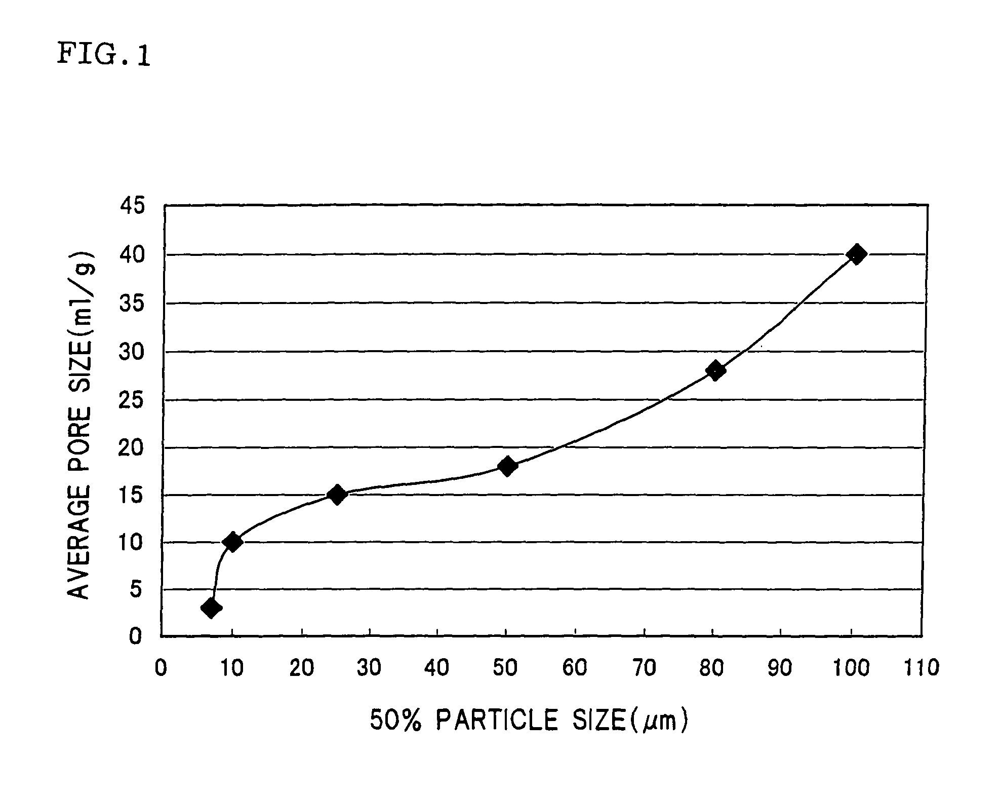
[0010]The first ceramic porous body according to the present invention does not produce carbon dioxide or toxic gas during firing and allows the firing time to be reduced in comparison with the case of using a resin powder or a carbon powder as the pore-forming agent by using the porous silica powder or the porous silica-containing compound powder as the pore-forming agent during production. Moreover, a change in pore-forming characteristics or deformation of a formed product rarely occurs. The second ceramic porous body according to the present invention does not produce carbon dioxide or toxic gas during firing, allows a reduction in the firing time, and rarely causes a change in pore-forming characteristics or deformation of a formed product in the same manner as the first ceramic porous body by using the silica gel granules with a specific 50% particle size (D50) as the pore-forming agent during production. According to the first and second methods of producing a formed product according to the present invention, since the silica gel or the water-absorbing polymer particles, which are not easily crushed during kneading, deaerating, or forming and rarely cause deformation of a formed product, are used as the pore-forming agent during production, the pore-forming agent is not crushed even if a formed product is integrally formed or produced using a continuous forming machine, whereby a ceramic porous body which exhibits a high porosity and does not show defects such as deformation can be obtained by firing the resulting formed product.

Problems solved by technology

However, such a powder increases the firing time or produces carbon dioxide or toxic gas during firing due to high combustible content.
However, the hollow resin particles are easily crushed during kneading, deaerating, or forming, whereby desired pore-forming characteristics may not be achieved.
In particular, when integrally forming a hard formed product or producing a formed product using a continuous forming machine, the hollow resin particles such as a resin foam exhibiting poor mechanical strength are easily crushed, thereby making it difficult to obtain a ceramic porous body with a high porosity.
However, since the combustibles cannot be eliminated, a problem similar to that arising when using the carbon powder or the like occurs to a certain extent.

Method used


Image

  • Ceramic porous body and method for producing molded body

Examples


examples

[0064]The present invention is described below in more detail by way of examples. Note that the present invention is not limited the following examples.

examples 19 to 21

[0078]Silica gel granules with different values for D50, D10 / D50, or D90 / D50 were provided. These silica gel granules were used as raw material granules. The raw material granules were sieved through a screen with a pore diameter of 145 μm. Cordierite porous bodies were obtained in the same manner as in Example 11 using the sieved silica gel granules as the pore-forming agent. The porosity and the average pore size of the resulting cordierite porous bodies were measured. The results are shown in Table 4. The raw material granules were sieved using an air jet classifier (“Fine Sifter MTS-D101” manufactured by Okawara Corporation) provided with a cylindrical screen with a pore diameter of 145 μm. The raw material granules were supplied to the internal space of the cylindrical screen, and sieved while absorbing the raw material granules from the outside of the cylindrical screen utilizing the force of the wind.

[0079]

TABLE 4Example 19Example 20Example 21Pore-forming agentD10(μm)2.72.87....

examples 22 to 26

[0081]Cordierite porous bodies were obtained in the same manner as in Example 11 using silica gel granules with different values for D10 / D50 or D90 / D50. The porosity and the average pore size of the cordierite porous bodies were measured. The results are shown in Table 5.

[0082]

TABLE 5Example 22Example 23Example 24Example 25Example 26Pore-forming agentD10(μm)1.52.55.87.512.5D502525242725D90140125756250D10 / D500.060.100.240.280.5D90 / D505.65.23.12.32Porous bodyPorosity(vol %)5248505352Average(μm)1017181925pore size

[0083]The cordierite porous bodies of Examples 23 to 26 in which the silica gel granules with a ratio D10 / D50 of 0.1 to 0.5 and a ratio D90 / D50 of 2 to 5 were used as the pore-forming agent had an average pore size of 10 μm or more which is required for a DPF.

[0084]The cordierite porous body of Example 22, in which the silica gel granules with a ratio D10 / D50 and a ratio D90 / D50 outside the above ranges were used as the pore-forming agent, had a significantly reduced average p...


PUM

PropertyMeasurementUnit
densityaaaaaaaaaa
porosityaaaaaaaaaa
particle sizeaaaaaaaaaa

Abstract

A ceramic porous body including at least Si as a chemical component, the ceramic porous body being obtained by adding a porous silica powder or a porous silica-containing compound powder to a forming raw material to prepare a clay, forming the resulting ceramic clay into a specific shape, and firing the formed product. The ceramic porous body according to the present invention does not produce carbon dioxide or toxic gas during firing and allows the firing time to be reduced in comparison with the case of using a resin powder or a carbon powder as a pore-forming agent by using the porous silica powder or the porous silica-containing compound powder as the pore-forming agent during production. Moreover, a change in pore-forming characteristics or deformation of a formed product rarely occurs.

Description

TECHNICAL FIELD[0001]The present invention relates to a ceramic porous body used for filters, catalyst carriers, and the like. More particularly, the present invention relates to a ceramic porous body which does not produce a toxic gas during production and rarely causes a change in pore-forming characteristics or deformation of a formed product.BACKGROUND ART[0002]A ceramic porous body has been widely used for filters, catalyst carriers, and the like. For example, the ceramic porous body has been used for an exhaust gas purifying device provided in a heat engine such as an internal combustion engine or combustion equipment such as a boiler, a liquid fuel / gaseous fuel reforming device, a service water / sewage purification device, and the like. The ceramic porous body is generally obtained by adding a pore-forming agent to a ceramic powder, adding a binder, forming agent, water, and the like to the mixture, kneading the resulting mixture, forming the kneaded product into a specific sh...

Claims


Application Information

Patent Timeline
Patent Type & Authority Patents(United States)
IPC IPC(8): C04B35/03B01D39/06B28B1/00B28B3/00C04B35/64B28B5/00C04B33/32C04B33/36C04B35/195C04B38/00C04B38/06C04B38/08
CPCC04B35/195C04B35/6263C04B38/0006C04B38/06C04B38/08C04B33/13C04B40/0268C04B35/14C04B38/0051C04B2235/77C04B2235/5436C04B2235/5427C04B2235/528C04B2235/349C04B2235/3445C04B2235/3418C04B2235/3218C04B2111/00793C04B2111/0081C04B2235/3217
Inventor HAYASHI, SHINZOUSUENOBU, HIROYUKIYAMADA, HIROTAKENOGUCHI, YASUSHI
Owner NGK INSULATORS LTD
Why Eureka
Try Eureka