Coherent shader output for multiple targets

a shader output and shader technology, applied in the field of graphics processors, can solve the problems of lack of coherence, reducing so as to reduce the overall efficiency of the gpu, the overhead of opening and closing dram pages, and the cost of accessing the dram pag

Active Publication Date: 2010-06-01
NVIDIA CORP
View PDF4 Cites 18 Cited by
  • Summary
  • Abstract
  • Description
  • Claims
  • Application Information

AI Technical Summary

Benefits of technology

[0008]A limitation with MRT is that each render target or buffer is typically allocated as a contiguous region in memory. However, render targets are typically large enough that they lie in different DRAM pages. A minimum number of reads or writes to a particular DRAM page are desired to cover the “cost” or overhead of accessing the DRAM page. The cost of opening and closing DRAM pages is typically overhead of “dead” cycles in which the DRAM is not able to read or write useful data. Therefore, unless at least a minimum amount of work is done within each DRAM page, the overhead involved in opening and closing the DRAM pages reduces the overall efficiency of the GPU.
[0009]As described further herein, at least a minimum number of writes should be done within each opened DRAM page to use the DRAM efficiently; writing fewer than the minimum number in the opened DRAM page reduces overall memory throughput. Discontinuous writes to memory can result in a lack of coherence, or inefficiency, in memory accesses to the frame buffer.

Problems solved by technology

A limitation with MRT is that each render target or buffer is typically allocated as a contiguous region in memory.
However, render targets are typically large enough that they lie in different DRAM pages.
The cost of opening and closing DRAM pages is typically overhead of “dead” cycles in which the DRAM is not able to read or write useful data.
Therefore, unless at least a minimum amount of work is done within each DRAM page, the overhead involved in opening and closing the DRAM pages reduces the overall efficiency of the GPU.
Discontinuous writes to memory can result in a lack of coherence, or inefficiency, in memory accesses to the frame buffer.

Method used


Image

  • Coherent shader output for multiple targets
  • Coherent shader output for multiple targets
  • Coherent shader output for multiple targets

Examples


Embodiment Construction

System Overview

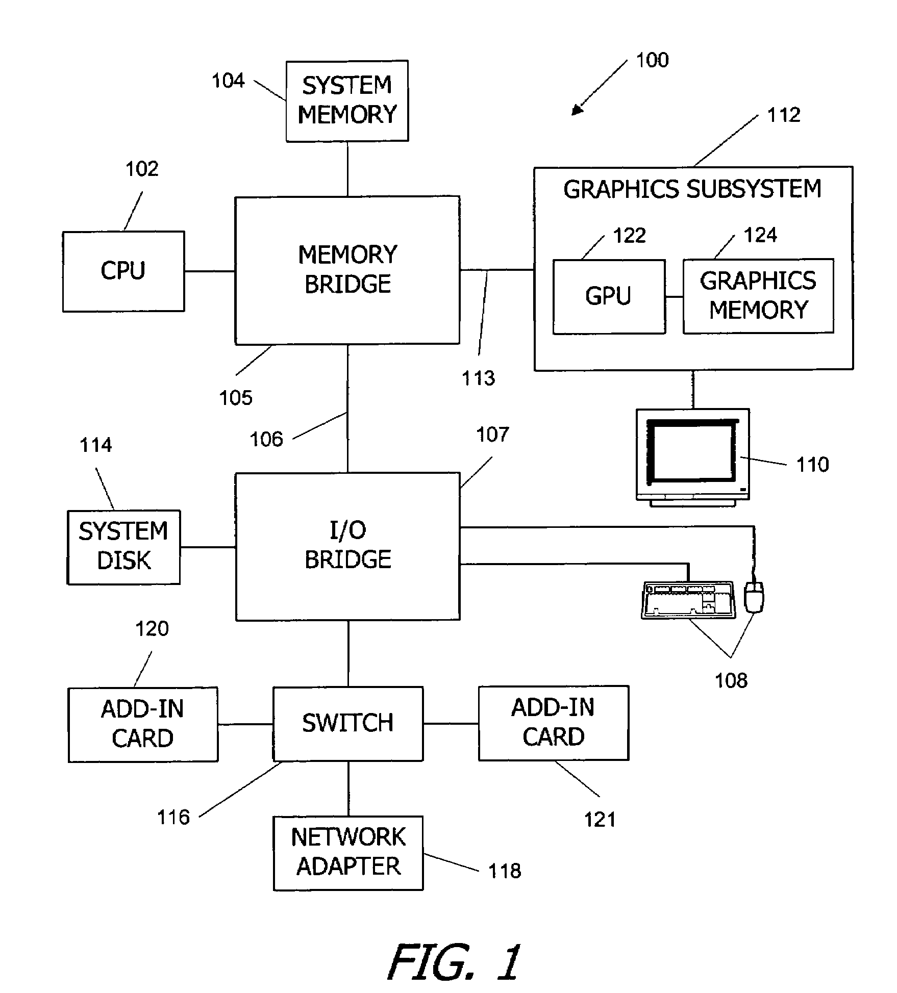
[0024]FIG. 1 is a block diagram of a computer system 100 according to an embodiment of the present invention. Computer system 100 is merely exemplary, and a number of alterations may be made to computer system 100. Computer system 100 includes a central processing unit (CPU) or control processor 102 and a system memory 104 communicating via a communications path that includes a memory bridge 105. Memory bridge 105 (e.g. a Northbridge chip) is connected via a communication path 106 (e.g., a point-to-point connection using the HyperTransport protocol) to an I / O (input / output) bridge 107. I / O bridge 107 (e.g. a Southbridge chip) receives user input from one or more user input devices 108 (e.g., keyboard, mouse) and forwards the input to CPU 102 via communication path 106 and memory bridge 105. Visual output is provided on a pixel based display device 110 (e.g., a CRT or LCD based monitor) operating under control of a graphics subsystem 112 coupled to memory bridge 105 vi...


PUM


Abstract

In a multiple render target mode, a pixel shader computes color values for pixels and stores the computed color values in a register file. The register file acts as a buffer for the computed color values. Conventionally writing pixels in the order they are received (pixel-major order) can result in large strides across memory in the frame buffer. At least a minimum amount of work should be done within a DRAM page, for example, to cover the overhead required in opening the DRAM page. Therefore, color values are written from the register file to two or more targets in a frame buffer in a target-major order within a segment. Writing in a target-major order (sequential with respect to targets but non-sequential with respect to quads received and processed) yields coherent writes to frame buffer memory and improves memory efficiency.

Description

CROSS-REFERENCE TO RELATED APPLICATIONS[0001]The present application claims priority to U.S. Provisional Patent Application No. 60 / 752,265, filed Dec. 19, 2005, entitled “Parallel Array Architecture For a Graphics Processor,” the disclosure of which is incorporated by reference herein as if set forth fully.BACKGROUND OF THE INVENTION[0002]The present invention relates in general to graphics processors, and in particular to systems and methods for writing graphics data for multiple (two or more) render targets from a graphics processor in a coherent fashion.[0003]Graphics processing is an important feature of modern high-performance computing systems. In graphic processing, mathematical procedures are implemented to render (draw) graphic primitives such as triangles on a display to produce desired visual images. Real time graphics processing is based on the high-speed processing of graphic primitives to produce visually pleasing moving images.[0004]Graphics processing is typically pe...

Claims


Application Information

Patent Timeline
Patent Type & Authority Patents(United States)
IPC IPC(8): G06F13/28G06F15/16G06T15/00
CPCG06T15/005G09G5/393G09G5/363G06T2210/52G09G2360/122G09G2360/06G06F15/80G06F15/8015G06F15/76G06T1/00
Inventor NORDQUIST, BRYONMOLNAR, STEVEN
Owner NVIDIA CORP
Why Eureka
Try Eureka