Graphene-based transistor
- Summary
- Abstract
- Description
- Claims
- Application Information
AI Technical Summary
Benefits of technology
Problems solved by technology
Method used
Image
Examples
first embodiment
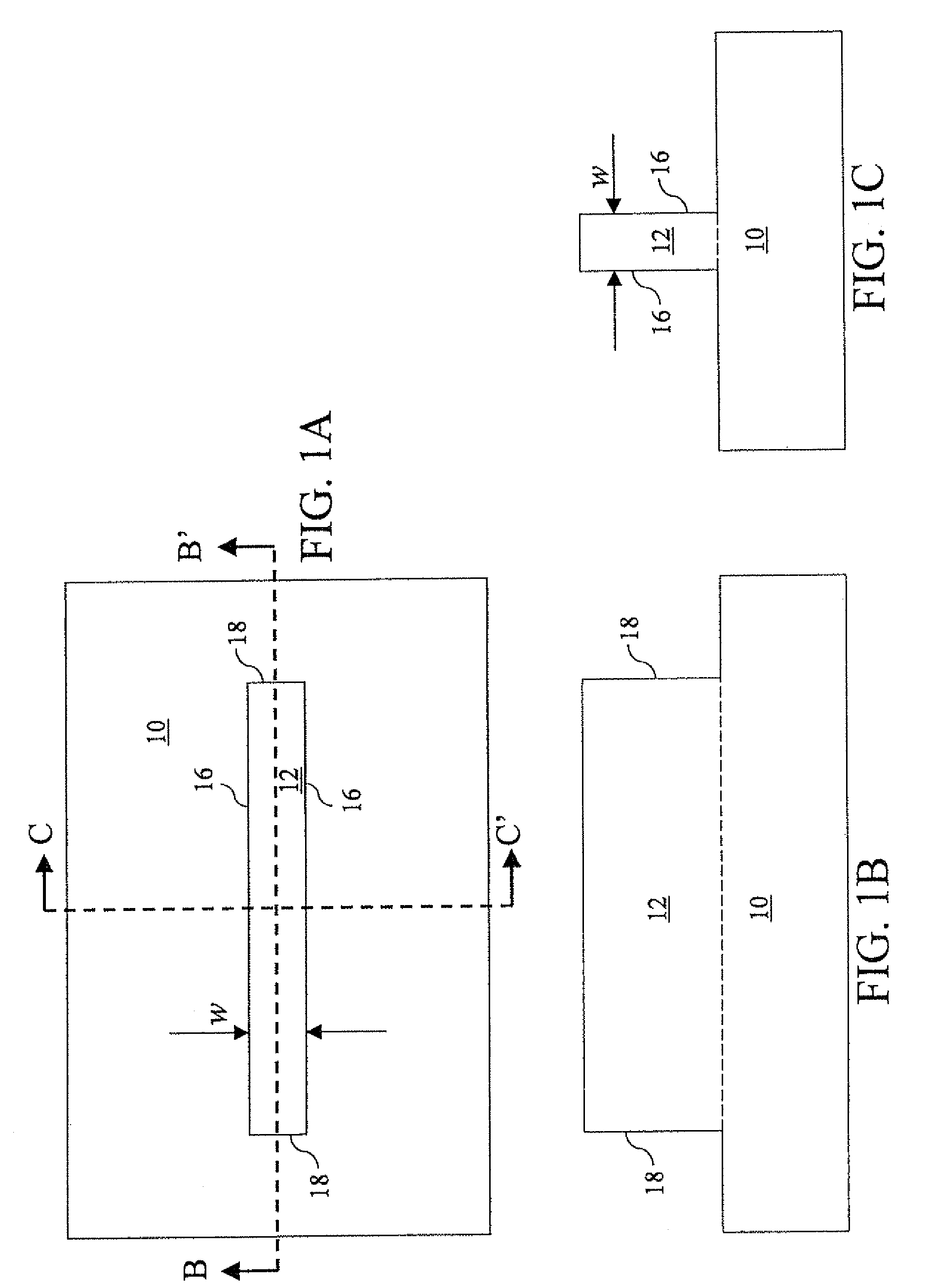
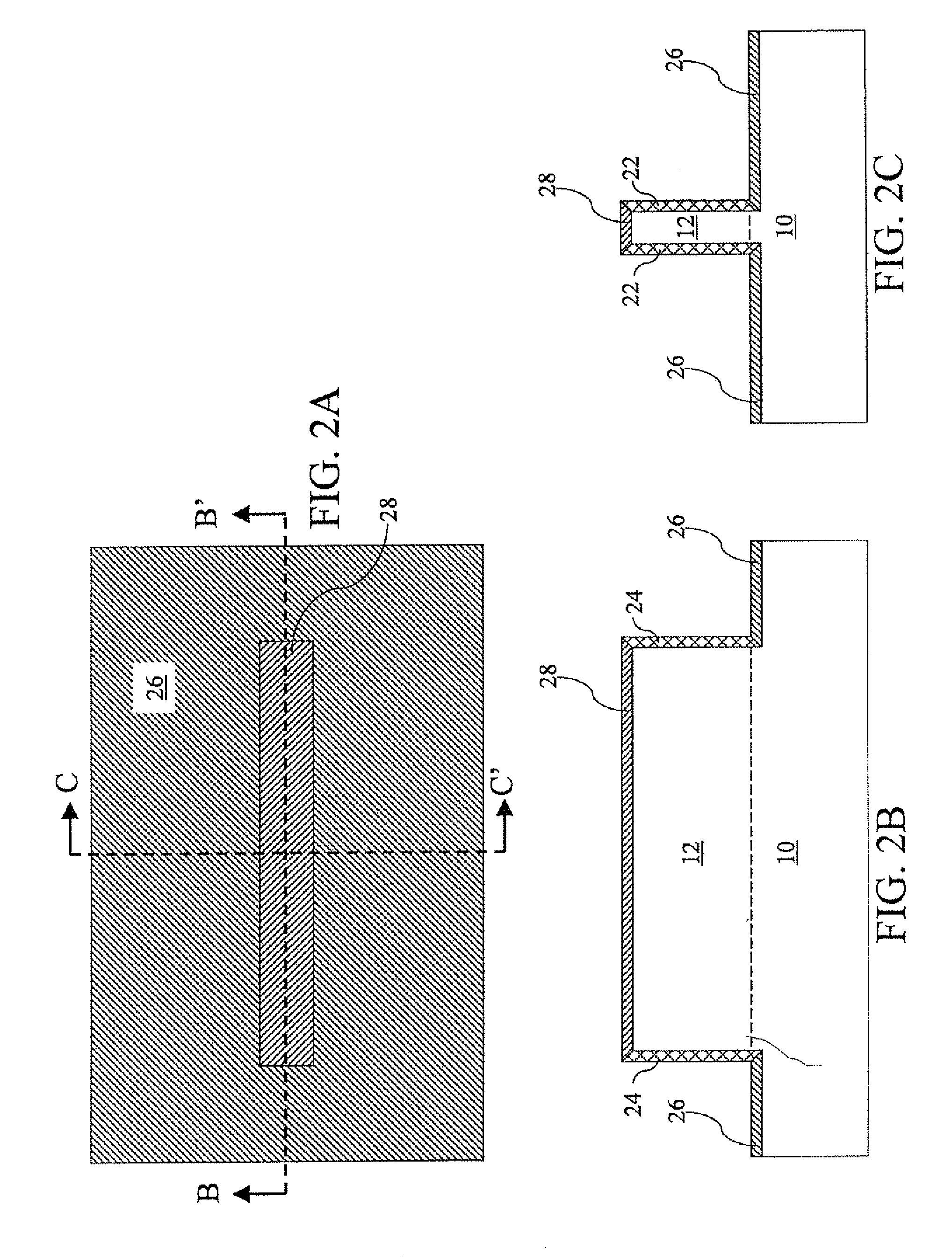
[0066]According to the present invention, a silicon carbide fin 12 formed on a silicon carbide substrate 10 is shown in FIGS. 1A-1C. The silicon carbide fin 12 is formed out of the silicon carbide substrate 10 by lithographic patterning and etching. For example, a photoresist (not shown) may be applied over a top surface of a planar initial silicon carbide substrate (not shown). After a lithographic patterning of the photoresist, the pattern in the photoresist is transferred into the planar initial silicon carbide substrate to form the silicon carbide fin 12 and the silicon carbide substrate 10 underneath. The portion of the silicon carbide substrate 10 that is covered by the photoresist corresponds to the silicon carbide fin 12. The interface between the silicon carbide fin 12 and the silicon carbide substrate 10 is marked by dotted lines in FIGS. 1B and 1C.
[0067]Preferably, the silicon carbide fin 12 comprises a first pair of sidewalls 16 that are substantially parallel to each ot...
second embodiment
[0084]According to the present invention, a trench 11 having a substantially flat bottom surface 13 and a pair of trench sidewalls 17 is formed in a silicon carbide substrate 10 as shown in FIG. 12. The trench 11 is formed within the silicon carbide substrate 10 by lithographic patterning and etching. For example, a photoresist (not shown) may be applied over a planar top surface of the silicon carbide substrate 10 followed by a lithographic patterning of the photoresist. The pattern in the photoresist is transferred into the silicon carbide substrate 10 to form the silicon carbide fin 12. The portion of the silicon carbide substrate 10 that is not covered by the photoresist corresponds to the trench 11.
[0085]Preferably, the depth d of the trench 11 exceeds the depth of source and drain regions to be subsequently formed. The crystallographic orientations of the silicon carbide substrate 10 are chosen such that the substantially flat bottom surface 13 is conducive to formation of a g...
third embodiment
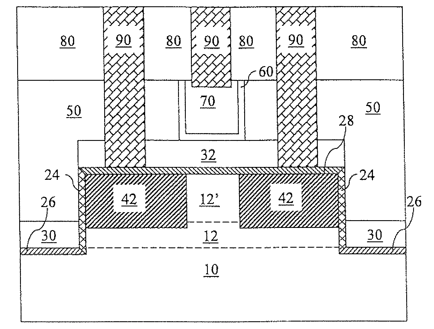
[0109]Referring to FIG. 31, an alternative field effect transistor structure according to the present invention does not contain the gate spacers 62.
PUM
 Abstract
Description
Claims
Application Information
 - R&D
- Intellectual Property
- Life Sciences
- Materials
- Tech Scout
- Unparalleled Data Quality
- Higher Quality Content
- 60% Fewer Hallucinations
Browse by: Latest US Patents, China's latest patents, Technical Efficacy Thesaurus, Application Domain, Technology Topic, Popular Technical Reports.
© 2025 PatSnap. All rights reserved.Legal|Privacy policy|Modern Slavery Act Transparency Statement|Sitemap|About US| Contact US: help@patsnap.com


