Implantable connector with protected contacts

a technology of protected contacts and connectors, applied in the direction of coupling device connections, diagnostic recording/measure, therapy, etc., can solve the problems of inability to pre-engage leads with compressible contacts, burden on connector clamping hardware, and inability to prevent inadvertent deformation of leads, so as to reduce structural loading and prevent inadvertent deformation. , the effect of low clamping for

Inactive Publication Date: 2010-06-15
SOCHOR JERZY ROMAN
View PDF6 Cites 179 Cited by
  • Summary
  • Abstract
  • Description
  • Claims
  • Application Information

AI Technical Summary

Benefits of technology

[0015]The receptacle contact is structurally integrated with the contact guard, which defines the mating lead contact seating envelope and protects the receptacle contact from an accidental damage. The contact guard protectively shields the receptacle contact's spring tines, thus preventing their inadvertent deformation and, preferably, maintains desirable contact gap by preloading the receptacle contact tines. A small but robust contact system is possible with the use of the contact guard. The contact guard protection enables use of a miniaturized contact which would otherwise be impractical due to susceptibility of the miniature contact to handling damage (e.g., from a mismated lead-seal assembly or inadvertent contact with a surgical tool).
[0016]The receptacle contact self-sustains contact normal forces; this reduces the structural loading required to support contact mating forces and therefore the size of the clamping hardware components. For example, the low clamping force enables use of small-sized clamping cover and space-efficient retention clips, which can be easily installed and removed without use of tools. (A provision for use of a simple screwdriver or a temporary external tool is also provided.)
[0017]The contact guard can be an integral part of the feedthrough pin or a separate component joined to the feedthrough pin. In some contact embodiments the contact guard can also provide contact tine preloading, which helps to reduce contact engagement force and assures consistent contact normal force.

Problems solved by technology

The compressible spring contacts extend above the exterior (outwardly facing) surface of the dielectric substrate and thus are susceptible to a handling damage (e.g., due to unintended contact with a human hand, a surgical tool, or a mismated component) if made too fragile.
On the other hand, a robust compressible spring contact (for adequate handling integrity) and a relatively large seal increase burden on connector clamping hardware, requiring a substantial clamping cover and screw.
Another issue in miniature implantable connectors is protection of the implantable leads from handling damage, especially during intra-operative attachment of the leads to the connector.
(In general, it is not feasible to pre-engage leads with compressible contacts since, in the absence of the sustaining clamping force, the compressible contacts will simply push back the lead.)

Method used


Image

  • Implantable connector with protected contacts
  • Implantable connector with protected contacts
  • Implantable connector with protected contacts

Examples


Embodiment Construction

FIGS. 1-10

Connector with Stamped Contact Guard

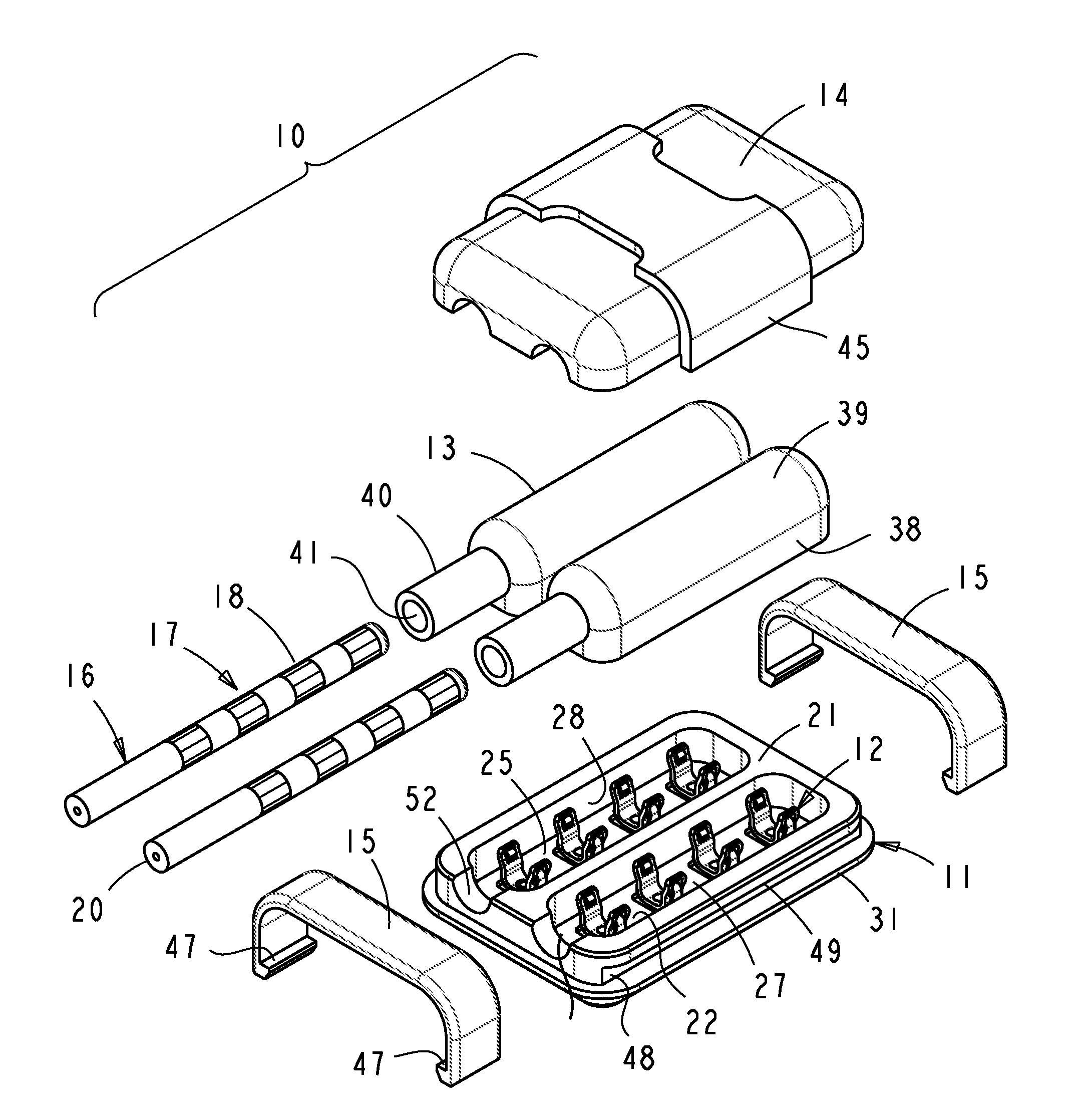
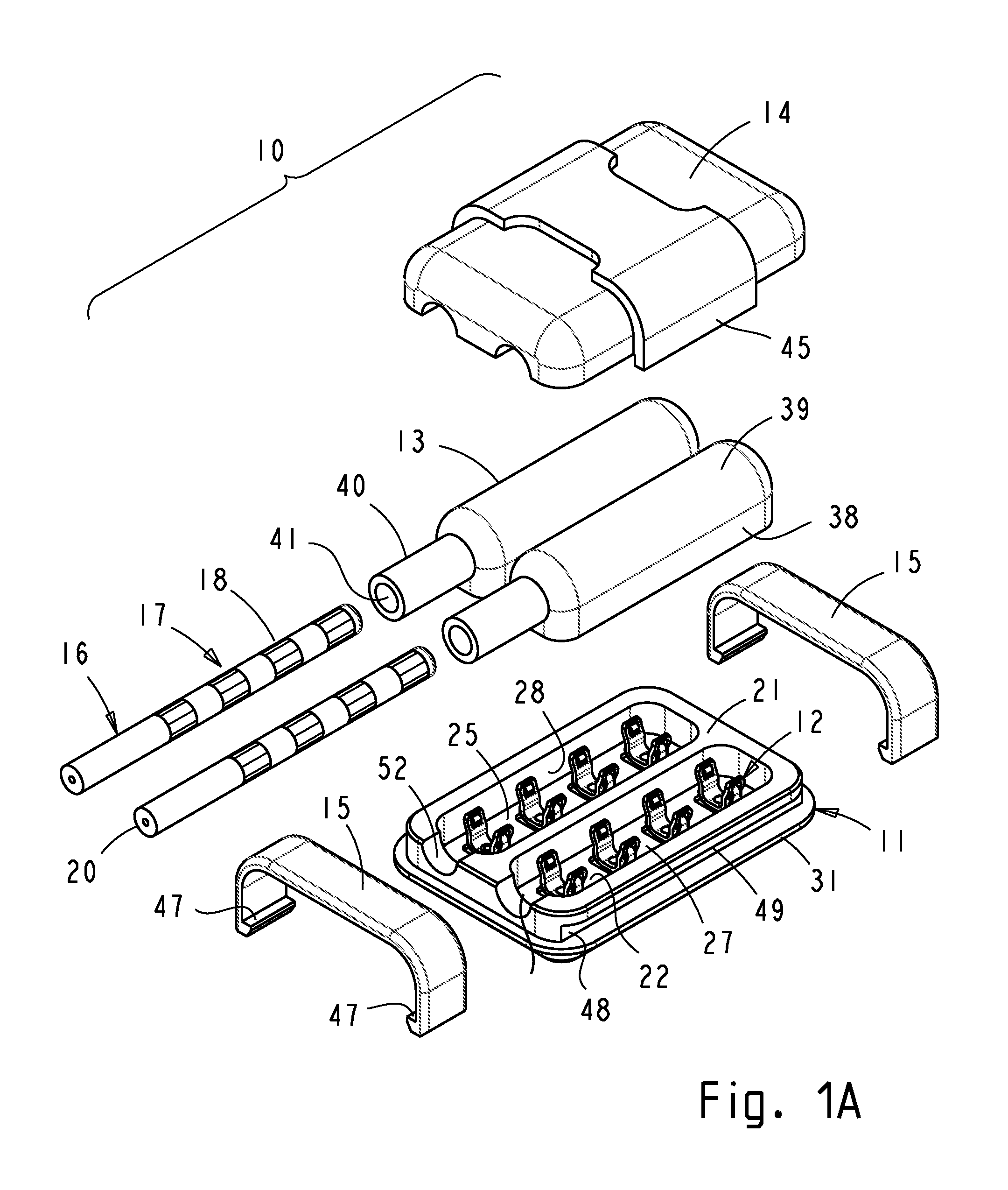
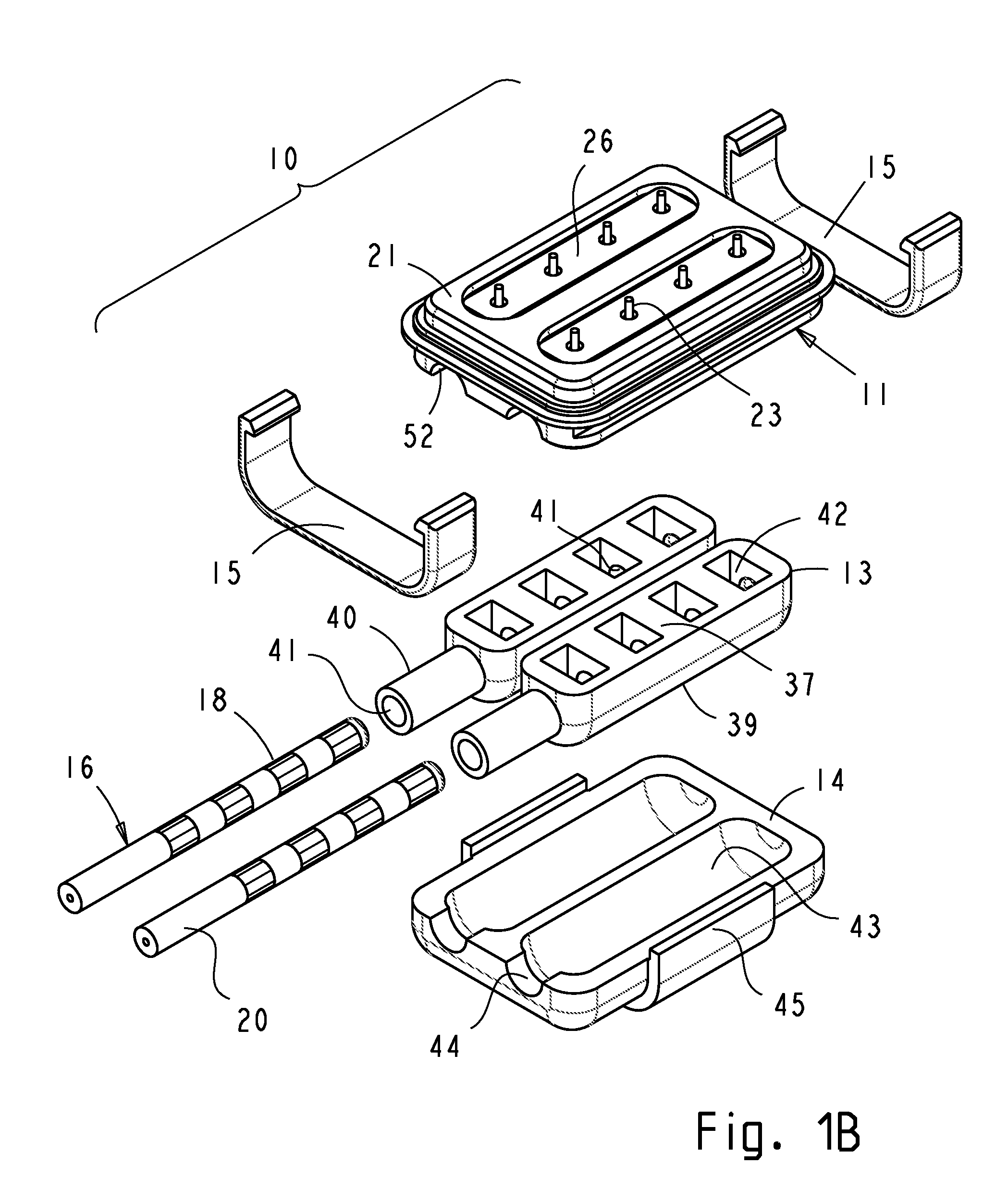
[0040]FIGS. 1A and 1B are exploded perspective views, top and bottom views respectively, of an implantable connector 10 which comprises a hermetic feedthrough 11, receptacle contact assemblies 12, seals 13, and a clamping means comprising a clamping cover 14 and retention clips 15.

[0041]Connector 10 provides a mating interface for two leads 16. Only lead ends proximal to the connector are shown. Each lead proximal end 17 has plurality of lead contacts 18, which typically have a tubular or ring form. The lead contacts are joined and electrically connected to respective conductors 19 of the lead (FIG. 1C). The conductors are confined within an insulating lead body 20 and connect to the respective sensing and / or stimulating electrodes at the lead's distal end. The lead's distal end, containing the electrodes, is implanted in body tissue targeted for sensing and / or stimulation (not shown; the method of such implantation is well known in the ...


PUM


Abstract

An implantable connector electrically connects multi-conductor leads to an implantable medical device such as a neurostimulator. The connector is assembled directly into a hermetic feedthrough of the implantable device and utilizes the feedthrough housing as a sustaining structure for connector clamping. The receptacle contacts detachably connect proximal lead contacts to corresponding feedthrough pins, which provide pass-through connections to electronic circuitry contained in a hermetically sealed case. The receptacle contact has resilient contact tines designed to engage a corresponding lead contact in a sliding manner. The receptacle contact is integrated with a contact guard which protects the receptacle contact from inadvertent handling damage. The contact guard is substantially more rigid than the resilient contact to resist deformation. The contact guard protectively shields the receptacle contact tines and prevents unintended contact tine excursion. In one embodiment, the contact guard is pre-attached to the receptacle contact prior to joining to the feedthrough pin. In another embodiment, the contact guard is an integral part of the feedthrough pin. Numerous embodiments with contact preload are provided.

Description

CROSS-REFERENCE TO RELATED APPLICATION[0001]This application claims priority of provisional patent application Ser. No. 61 / 056,086, filed 2008 May 27 by the present inventor.BACKGROUNDPrior Art[0002]A typical implantable electronic device, such as a cochlear implant, cardiac pacemaker, or a neurostimulator, has electronic circuitry (electronics) that is contained in a hermetic housing or case. The device has attached at least one multi-conductor lead that has sensing and / or stimulating electrodes on its end which is distal from the device and which is implanted in the tissue targeted for therapy (cochlea, heart muscle, particular area of brain, etc.). Other leads may connect the device to additional implantable system components, such as drug delivery devices, implantable inductive coils (for energy delivery to the device and / or data communication with the device), or power sources, which may have to reside in a more accessible body area for easier charging and / or replacement.[0003]...

Claims


Application Information

Patent Timeline
Patent Type & Authority Patents(United States)
IPC IPC(8): H01R24/04H01R24/58
CPCA61N1/3752H01R24/58H01R13/5224A61N1/3754H01R2201/12H01R2107/00Y10S439/909
Inventor SOCHOR, JERZY ROMAN
Owner SOCHOR JERZY ROMAN
Why Eureka
Try Eureka