

Membrane separation of feed and growth environments in carbon nanostructure growth
a carbon nanotube and growth environment technology, applied in the direction of crystal growth process, polycrystalline material growth, chemically reactive gas, etc., can solve the problems of cost and time-consuming post-process purification, and achieve the effect of reducing mass transport limitations, high purity, and cost and time-consuming
Inactive Publication Date: 2010-06-15
COLORADO SCHOOL OF MINES
View PDF17 Cites 4 Cited by
- Summary
- Abstract
- Description
- Claims
- Application Information
AI Technical Summary
Benefits of technology
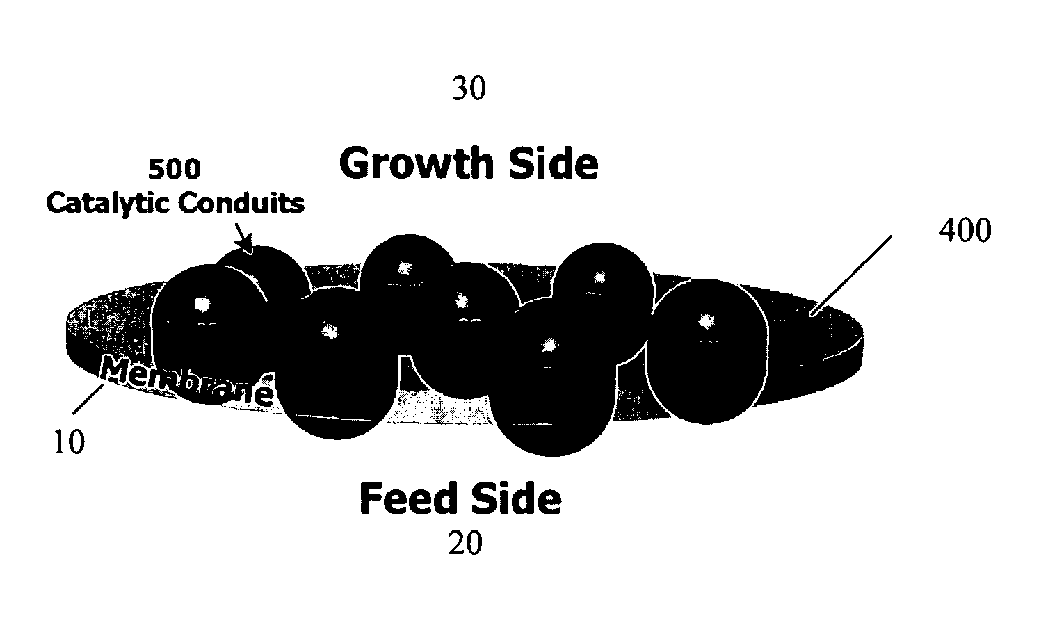
[0015]The invention provides CVD-based methods for growing single-walled or multi-walled carbon nanotubes. In conventional CVD-based methods, the CVD decomposition environment is shared by the nanotube growth environment. In the methods of the invention, the nanotube growth environment is separated from the carbon-containing gas feed environment, resulting in nanotubes of high purity, uncontaminated by other carbon phases. Therefore, costly and time-consuming post processing purification to remove unwanted carbon phases is not required. The methods of the invention can also avoid catalyst inactivation by unwanted carbon phases, e.g. by applying water vapor pulses in the carbon-containing gas feed environment, and reduce mass transport limitations and thus increase the length of the carbon nanotubes formed.
[0020]The methods of the invention provide improved mass transport of carbon to the catalyst at the growth side of the membrane as compared to other CVD processes. When a solid non-porous membrane is used to separate the nanotube growth and reaction gas environments, the relevant mode of carbon transport will be diffusion of carbon through the membrane. In contrast, in conventional CVD methods the relevant mode of carbon transport to the catalyst is transport of gaseous carbon-containing materials through the growing nanotube foliage to the catalyst.
[0021]In the methods of the invention, thermodynamic and kinetic parameters are selected that enhance CNT growth and limit formation of byproducts. These parameters can be specially tailored for each side of the membrane. The thermodynamic conditions (temperature, pressure, molar ratios, constituents) on the feed side can be controlled to maximize the catalytic cracking of carbon feedstock materials while minimizing the formation of byproducts that can poison the decomposition process (such as the formation of amorphous carbons and turbostratic graphites). Addition of accelerators like molybdenum and promoters can be added exclusively to the feed side. If required, specifically designed thermodynamic conditions on the growth side maximize the purity of the carbon nanotubes. If required, the thermodynamic conditions on the growth side can also be selected to enhance the bundling process during the growth process, thereby eliminating costly post-purification procedures. Temperature can be regulated by resistive heating of the membrane, targeted infrared heating or by conventional cavity methods. Kinetic parameters such as the strategic placement of accelerators and nanostructuring of catalyst surfaces can be controlled independently for both sides. The addition of electric field to align tubes is also available for the growth side.
Problems solved by technology
Therefore, costly and time-consuming post processing purification to remove unwanted carbon phases is not required.
Method used
View moreImage
Smart ImageViewing Examples

Examples
example
Formation of a Membrane for Growth of Multi-Walled Nanotubes
[0083]A template is formed by creating nanoholes in either a Mo metal foil or a silica material (thickness 0.25 micron to 1 micron). The nanoholes (pores) are 20 nm, 30 nm, or 40 nm in diameter and are formed with nanolithography.
[0084]A layer (a few nm to greater than 5 nm thick) of alumina is applied to the interior of the nanoholes and the faces of the template via atomic layer deposition.
[0085]A catalyst containing Fe, Ni, or Co is then inserted into the nanoholes, substantially filling them. Subsequently, a Mo film is applied to the feed side of the membrane.
Login to View More PUM
| Property | Measurement | Unit |
|---|---|---|
| thickness | aaaaa | aaaaa |
| thickness | aaaaa | aaaaa |
| size | aaaaa | aaaaa |
Abstract
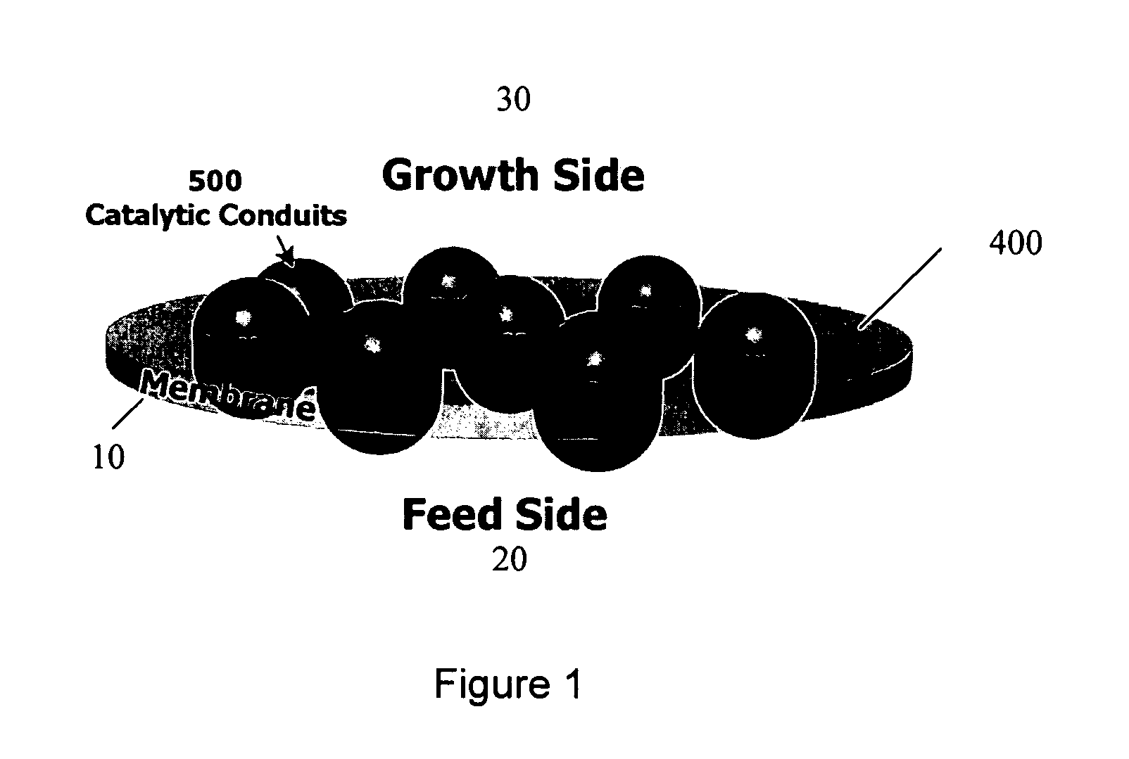
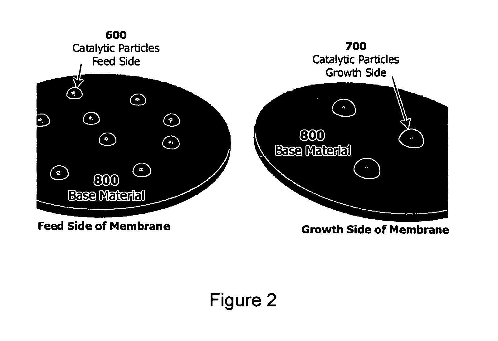
The invention provides CVD-based methods for growing single-walled or multi-walled carbon nanotubes. In the methods of the invention, the nanotube growth environment is separated from the carbon-containing gas feed environment using a membrane which is substantially impermeable to gas flow but permits diffusion of carbon through the membrane. A catalyst for carbon nanotube growth is located on the growth side of the membrane while a catalyst for decomposition of carbon-containing gas is located on the feed side of the membrane. A path for diffusion of carbon through the membrane is provided between the growth and decomposition catalysts. Control of the size and shape of the carbon nanotube growth catalyst enables control over the nanotube structure formed.
Description
CROSS-REFERENCE TO RELATED APPLICATIONS[0001]This application claims the benefit of provisional application 60 / 699,144 filed Jul. 14, 2005 which is hereby incorporated by reference to the extent not inconsistent with the disclosure herein.BACKGROUND OF THE INVENTION[0002]This invention is in the field of carbon nanomaterials, in particular, methods for making carbon nanotubes and carbon nanotube fibers.[0003]The term “carbon nanomaterials” is used generally herein to refer to any substantially carbon material containing six-membered rings that exhibits curving of the graphite planes, sometimes by including five-membered and / or seven membered rings amongst the hexagons formed by the positions of the carbon atoms, and has at least one dimension on the order of nanometers. Examples of carbon nanomaterials include, but are not limited to, fullerenes, single-walled carbon nanotubes (SWNTs), double-walled carbon nanotubes, multiple-walled carbon nanotubes (MWNTs), nanotubules, and nested ...
Claims
Login to View More Application Information
Patent Timeline
 Patent Type & AuthorityPatents(United States)
IPC IPC(8): D01F9/127D01F9/12
CPCB82Y30/00B82Y40/00C01B31/0233D01F9/133C30B25/16C30B29/602D01F9/127C01B2202/02C01B2202/06C01B2202/04C01B32/162
InventorLUSK, MARK THOMASHORNYAK, G. LOUISBURKE, MICHAEL THOMAS
OwnerCOLORADO SCHOOL OF MINES