Wave energy device

a wave energy and device technology, applied in the direction of sea energy generation, buoyancy control, electrical equipment, etc., can solve the problems of reducing the conversion efficiency, the engineering challenges necessary to enable the equipment to survive in that environment have so far proved insurmountable, and the realization of a cost-effective wave energy conversion technology. achieve the effect of increasing the buoyancy of the buoyant body

Inactive Publication Date: 2010-06-15
WAVE ENERGY TECH
View PDF17 Cites 14 Cited by
  • Summary
  • Abstract
  • Description
  • Claims
  • Application Information

AI Technical Summary

Benefits of technology

[0017]The device includes a buoyant body for tracking the rise and fall of the waves and a working surface coupled for movement with the buoyant body and which is designed to capture and convert both heave and surge forces of the waves for optimum efficiency in capturing wave energy. The shape of the working surface includes a lower portion extending downwardly and forwardly into the oncoming waves enhancing the ability of the device to capture wave energy to a substantial depth below the surface of the waves instead of relying only on buoyancy to drive upward movement of the buoyant body. Weight of the buoyant body or any additional ballast provided increase efficiency by driving the buoyant body downwardly into the troughs between adjacent wave crests.
[0021]Preferably a pair of upright side panels span between the upper portion and the lower portion horizontally spaced apart from one another at opposing ends of the working surface in which the side panels are spaced apart in a direction which is substantially perpendicular to the wave direction. The side panels may diverge from one another as the side panels extend forwardly from the inner ends to the outer ends of the portions of the working surface for increasing the capture area of the working surface.
[0034]It is independently advantageous to provide a variable ballast on the buoyant body which is operable to increase buoyancy of the buoyant body in the transport position in relation to the working position.
[0040]A rear side of the buoyant body opposite the working surface may be suitably shaped for reduced drag when towed across a surface of a body of water and may further include pontoons attached thereto having a longitudinal axis extending generally in the wave direction to assist in supporting the buoyant body in the transport position.
[0043]Baffles may be supported in the ballast chamber for limiting the movement of the water in the ballast chamber to increase stability of the buoyant body.
[0060]a variable ballast on the buoyant body operable to increase buoyancy of the buoyant body in the transport position in relation to the working position.

Problems solved by technology

However, their random nature and the hostility of the marine environment have posed significant problems to the practical realization of a cost-effective wave energy conversion technology.
However, the engineering challenges necessary to enable the equipment to survive in that environment have thus far proven to be insurmountable.
Another reason is that deepwater structures must float and this reduces the conversion efficiency.
Although incident power reduces with decreasing depth, so do construction, installation and operating costs.
However, a viable design for a wave energy converter operating at this depth or any other depth has not yet been demonstrated as commercially viable.
In each instance however, the floats are only able to capture the vertical movement of the water.
Accordingly, a substantial portion of the wave energy in the form of surge forces in the direction of wave propagation is lost, resulting in poor operating efficiencies.
The cost of installation of such a configuration is typically prohibitive.
Furthermore, the devices can be subject to considerable damage when left open to the elements due to the fixed nature of their installation.

Method used


Image

  • Wave energy device
  • Wave energy device
  • Wave energy device

Examples


Embodiment Construction

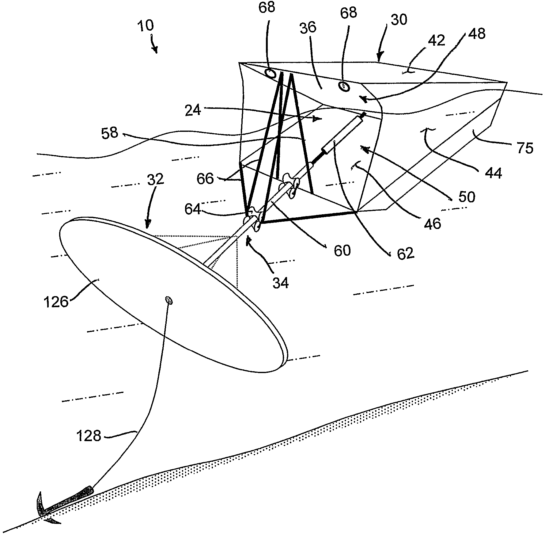
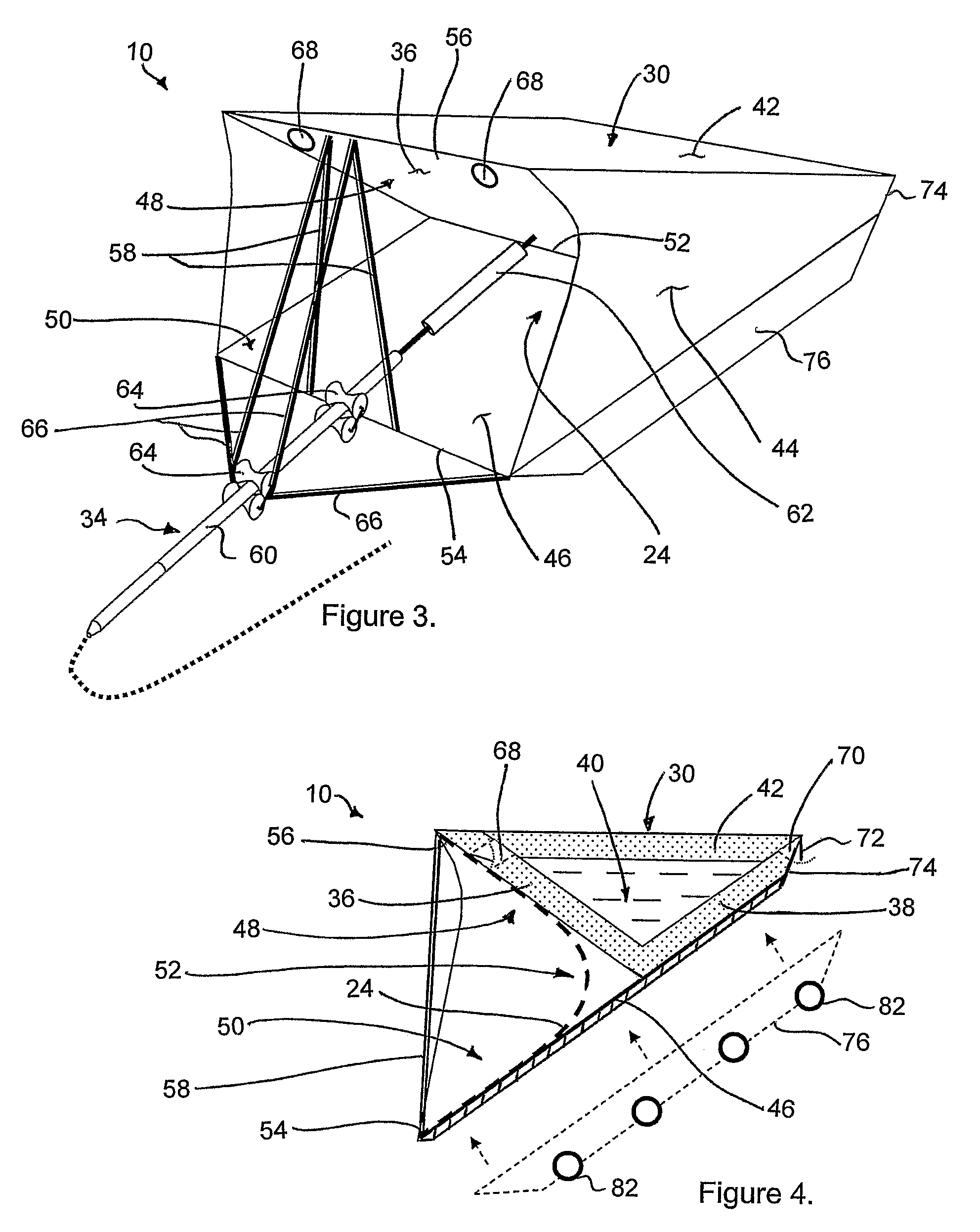
[0083]Referring to the accompanying figures there is illustrated a wave energy device generally indicated by reference numeral 10. The device 10 is particularly suited for capturing wave energy from waves propagating in a wave direction 12. The device 10 is arranged to convert the wave energy into a usable form of energy, for example electrical power or a flow of pressurized water which can be later used either at the wave energy device or at a remote location for desalinating seawater or for driving an electrical turbine generator.

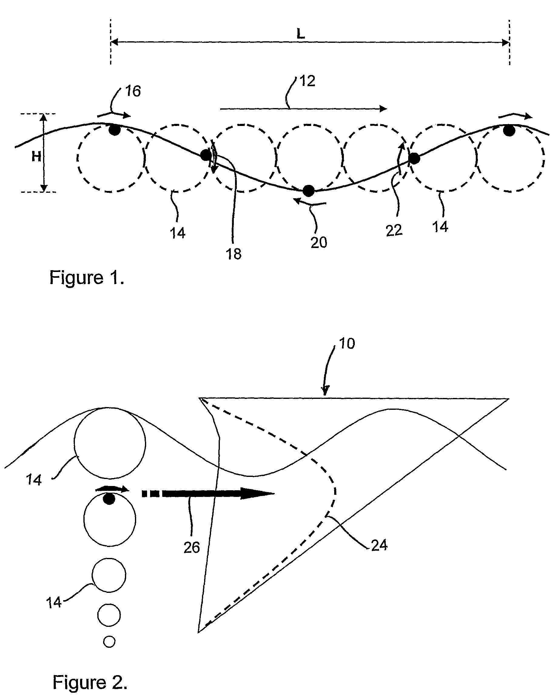
[0084]With initial reference to FIGS. 1 and 2, waves propagating in the wave direction 12 typically are comprised of water following generally orbital motions 14 advancing generally in a shoreward direction of wave propagation. As the water goes through orbital motions 14 the water forms a wave having a wavelength L between the crests of adjacent waves and a height H between each crest and the adjacent trough.

[0085]At the crest of each wave, at an upper p...


PUM


Abstract

A wave energy device converts the motion of waves on a body of water into a usable form of energy, for example a flow of pressurized water or an electrical current. The device includes a buoyant body for tracking the rise and fall of the waves and a working surface coupled for movement with the buoyant body and which is designed to capture and convert both heave and surge forces of the waves. The invention also involves a rapid deployment and retrieval capability and a capability to rotate to accommodate changes in wave direction. The device is universally attached to the seafloor, which allows the device to safely pitch, yaw and roll with the wave forces from any direction thereby reducing the likelihood of damage due to extreme weather or marine traffic. The universal attachment also allows the device to automatically adjust for varying water elevation due to tides.

Description

[0001]This application is a national phase filing of PCT / CA05 / 001808 and claims the benefit under 35 U.S.C. 119(e) of U.S. provisional application Ser. No. 60 / 632,305, filed Dec. 2, 2004.FIELD OF THE INVENTION[0002]The present invention relates to a wave energy device for capturing wave energy of waves to a substantial depth below the surface of a body of water, and more particularly relates to a device for capturing both heave and surge forces of the waves and converting the energy from the waves to a usable form, for example, a flow of pressurized water for purposes of the production of desalinated water or electric power.BACKGROUND[0003]The first of many patents for devices proposing to harness the power contained in ocean waves was issued in France in 1799. It was not until the 1970's that any considerable efforts were made to develop a viable and cost-effective technology. This was primarily driven by the increasing concern about the earth's finite fossil fuel resources and abo...

Claims


Application Information

Patent Timeline
Patent Type & Authority Patents(United States)
IPC IPC(8): F03B13/10F03B13/12H02P9/04
CPCF03B13/14F03B13/182F03B13/1875F05B2270/18F05B2250/712Y02E10/38Y02E10/30
Inventor VOWLES, ALANKURCZABA, BRIANACRES, HEATHER
Owner WAVE ENERGY TECH
Why Eureka
Try Eureka