Remote drain and filter arrangement for a portable generator system

a portable generator and filter arrangement technology, applied in the direction of auxillary lubrication, lubricant mounting/connection, manufacturing tools, etc., can solve the problems of long engine life, inconvenient engine service, and difficulty in servicing the engine, so as to reduce the space required for implementing the engine driven welder and increase the functionality of the kit. , the effect of saving tim

Inactive Publication Date: 2010-06-22
ILLINOIS TOOL WORKS INC
View PDF14 Cites 10 Cited by
  • Summary
  • Abstract
  • Description
  • Claims
  • Application Information

AI Technical Summary

Benefits of technology

[0006]The current invention offers a unique, cost effective, and time saving solution to the inconveniencies created in servicing engine-driven generators and engine-driven welders. The invention generally consists of a kit that allows the oil filter to be positioned outside the enclosure of the generator. The kit includes an oil filter adapter that is used to interface with the oil filter and is coupled to the engine via oil conduits. The oil conduits allow the engine oil to be circulated between the engine and the filter. The kit further includes an oil drain conduit allowing the oil to be drained from a location outside of the enclosure. The kit can be mounted to the external portion of the enclosure or to a support surface on a vehicle. Furthermore, the space required to implement the engine driven welder can be reduced by mounting the oil adapter and oil drain conduit directly to the vehicle. The user can increase the functionality of the kit by incorporating a pump between the filter and engine, where desired.
[0007]Thus, the kit allows for tremendous flexibility in positioning these serviceable components, thereby allowing the user to choose the optimum configuration for their given situation. Furthermore, the current invention completely eliminates the need for the user to relocate or reposition the unit when performing an oil change. Thus, maintaining the engine is no longer a difficult and time consuming task, which leads to a secondary benefit of promoting regular engine maintenance. The current invention is completely retrofittable so that the user is not required to purchase a new generator or welder to enjoy the benefits offered by the current invention. Finally, the current invention can be incorporated into future designs and provided at the time of manufacturing.

Problems solved by technology

One issue with engine-driven generators and engine-driven welders relates to their weight and the positioning of the unit in order to perform routine oil changes and other engine maintenance.
Given that space is limited in these vehicles, the unit usually is placed adjacent to the cab of the vehicle and / or surrounded by permanently mounted tool boxes or other built-in structures of the vehicle.
Moreover, the engine and generator are typically fully enclosed by an enclosure and servicing the engine becomes difficult because direct access is at best very limited.
All of these benefits lead to longer component and engine life.
However, engine maintenance is critical to engine performance and is a task that must be performed at regular intervals.
Given the required regularity of the engine maintenance, the current inconveniencies of performing engine service can become a major issue for the user.
As alluded to above, the location of this panel is often blocked by nearby tool boxes or other structures.
Given the weight of the unit, this can be a very time consuming and arduous task.
While certain facilities have been provided by the ability to relocate oil filter and drain locations within the enclosure, even these do not alleviate the need to access the interior via panels and the like.

Method used


Image

  • Remote drain and filter arrangement for a portable generator system
  • Remote drain and filter arrangement for a portable generator system
  • Remote drain and filter arrangement for a portable generator system

Examples


Embodiment Construction

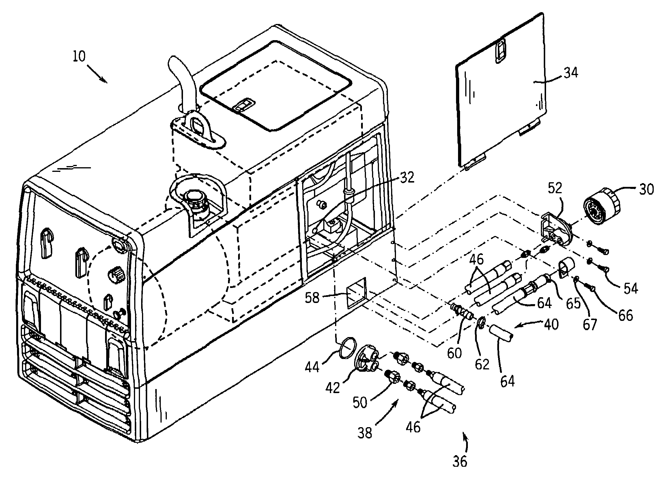
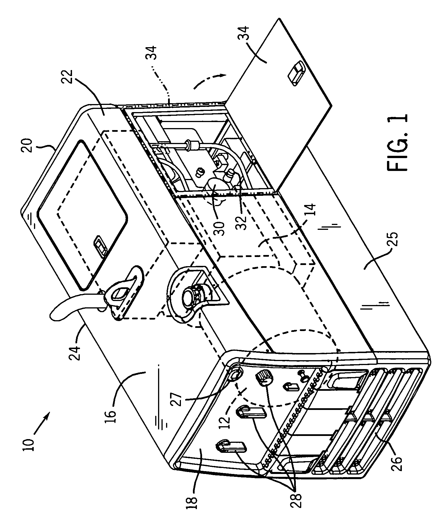
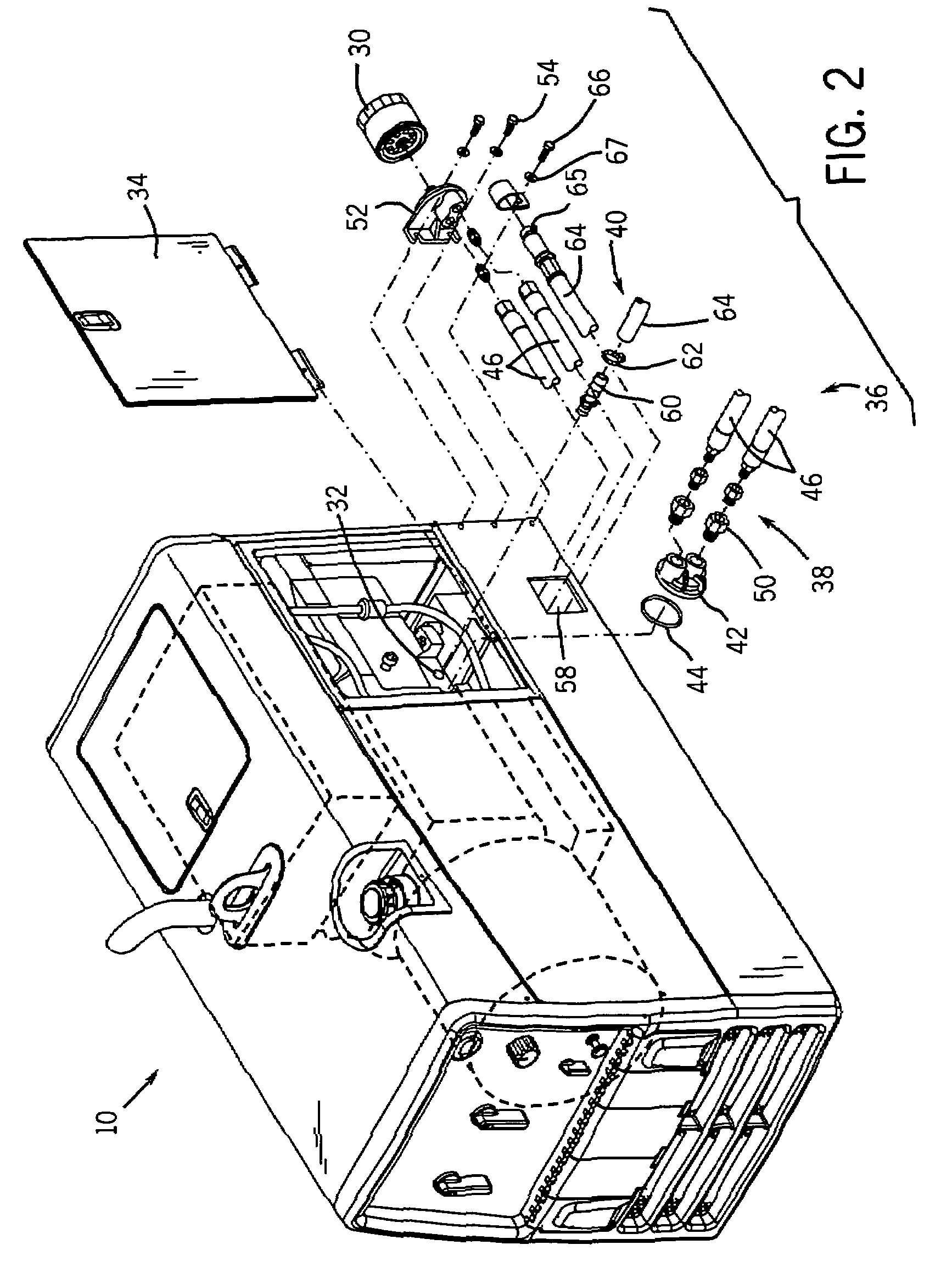
[0016]Turning now to the drawings, FIG. 1 illustrates the relevant elements of the engine-driven welder when the current invention is not used and all of the elements are located inside the enclosure. The engine-driven welder 10 includes an electrical power generator 12 that is coupled to and driven by an engine 14. The engine can be either a gasoline or diesel engine. Other engines may also be used for this purpose, including liquefied petroleum gas engines The engine and generator are fully enclosed by an enclosure 16. The enclosure consist of a front panel 18, a rear side 20, a right side 22, and a left side 24, all engaging a base 25 to complete the enclosure. The enclosure protects the engine and generator form dust, debris, and rough handling. The enclosure also reduces noise and helps to cool the engine by preventing hot air recirculation via the cool air inlet 26 pulling air through the interior volume of the enclosure.

[0017]A control system regulates the electrical power su...


PUM

PropertyMeasurementUnit
electric poweraaaaaaaaaa
volumeaaaaaaaaaa
electrical poweraaaaaaaaaa

Abstract

A remote drain and filter arrangement for a portable engine-driven generator is disclosed that positions the oil filter and oil drain at a location outside the enclosure of the generator. The arrangement generally consists of an oil filter assembly and oil drain assembly. The oil filter assembly includes an oil filter adapter used to interface with the oil filter and is coupled to the engine via oil conduits. The oil drain assembly includes an oil drain conduit and a flow control device that allows the oil to be drained from a location outside of the enclosure of the generator. A pump can be used to allow for sufficiently longer oil conduits. The invention is retrofittable to current engine-driven generators and can also be incorporated into future designs.

Description

BACKGROUND[0001]The invention relates generally to the field of portable engine-driven generators. More specifically, the inventions relates to a remote drain and filter arrangement that is used for an engine-driven generator or an engine-driven welder.[0002]Portable engine-driven generators are commonly used to provide electrical power in locations where conventional electrical power is not readily available. Both gasoline and diesel engines are used to drive such generators, and the power produced is typically either 120 VAC or 240 VAC. One specific generator application is for welding processes and these units are commonly known as portable engine-driven welders. These units include a control system to regulate the power produced by the generator thereby making it suitable for an arc welding operation. Typical welding operations for which these units are intended include stick electrode welding, MIG welding, TIG welding, or plasma torch cutting.[0003]One issue with engine-driven ...

Claims


Application Information

Patent Timeline
Patent Type & Authority Patents(United States)
IPC IPC(8): F01M11/03F01M11/10B23K9/10H05B7/11
CPCB23K9/32F01M11/03F02B63/04F01M11/0408F02B63/048
Inventor LEISNER, JOHN C.
Owner ILLINOIS TOOL WORKS INC
Why Eureka
Try Eureka