Method and apparatus for power electronics and control of plug-in hybrid propulsion with fast energy storage

a plug-in hybrid and energy storage technology, applied in the direction of propulsion by batteries/cells, propulsion by capacitors, transportation and packaging, etc., can solve the problems of deep cycling, reduced battery life, and inability to realize the full potential of conventional hybrid propulsion, so as to simplify the integration into the vehicle, limited battery life, and reduce the cost of batteries. and space consumption. , the effect of compact and inexpensiv

Inactive Publication Date: 2010-06-22
AFS TRINITY POWER CORP
View PDF14 Cites 187 Cited by
  • Summary
  • Abstract
  • Description
  • Claims
  • Application Information

AI Technical Summary

Benefits of technology

[0018]An advantage of the invention is that the resulting package is very compact and inexpensive compared to discrete drive units. Costly and space consuming interconnections are eliminated.
[0019]A second advantage of the invention is that radiated EMI is more readily contained.
[0020]An additional advantage of the invention is that subsystems such as liquid cooling can be shared, simplifying integration into a vehicle.
[0021]An additional advantage of the invention is that a single controller can implement an n-phase drive where the number of phases, n, may exceed 18.
[0022]The invention enables integration of electrochemical, electrostatic, and electrokinetic storage technology. The apparatus and its function have application in a wide range of vehicles as well as distributed energy systems.

Problems solved by technology

The main problem with existing conventional hybrids is that the full potential of conventional hybrid propulsion is not realized due to limited all-electric travel range.
The main problems with existing plug-in hybrid vehicles are the cost of batteries and limited battery life.
Deep cycling reduces battery life.
The plug-in hybrid battery is much larger and proportionately more expensive than the battery in a conventional hybrid vehicle.
Therefore, the cost penalty associated with a plug-in hybrid is more severe than for a conventional hybrid.
An additional problem with batteries used for hybrid vehicles is that maximizing available energy storage requires constraining such environmental conditions of the batteries as temperature.

Method used


Image

  • Method and apparatus for power electronics and control of plug-in hybrid propulsion with fast energy storage
  • Method and apparatus for power electronics and control of plug-in hybrid propulsion with fast energy storage
  • Method and apparatus for power electronics and control of plug-in hybrid propulsion with fast energy storage

Examples


Embodiment Construction

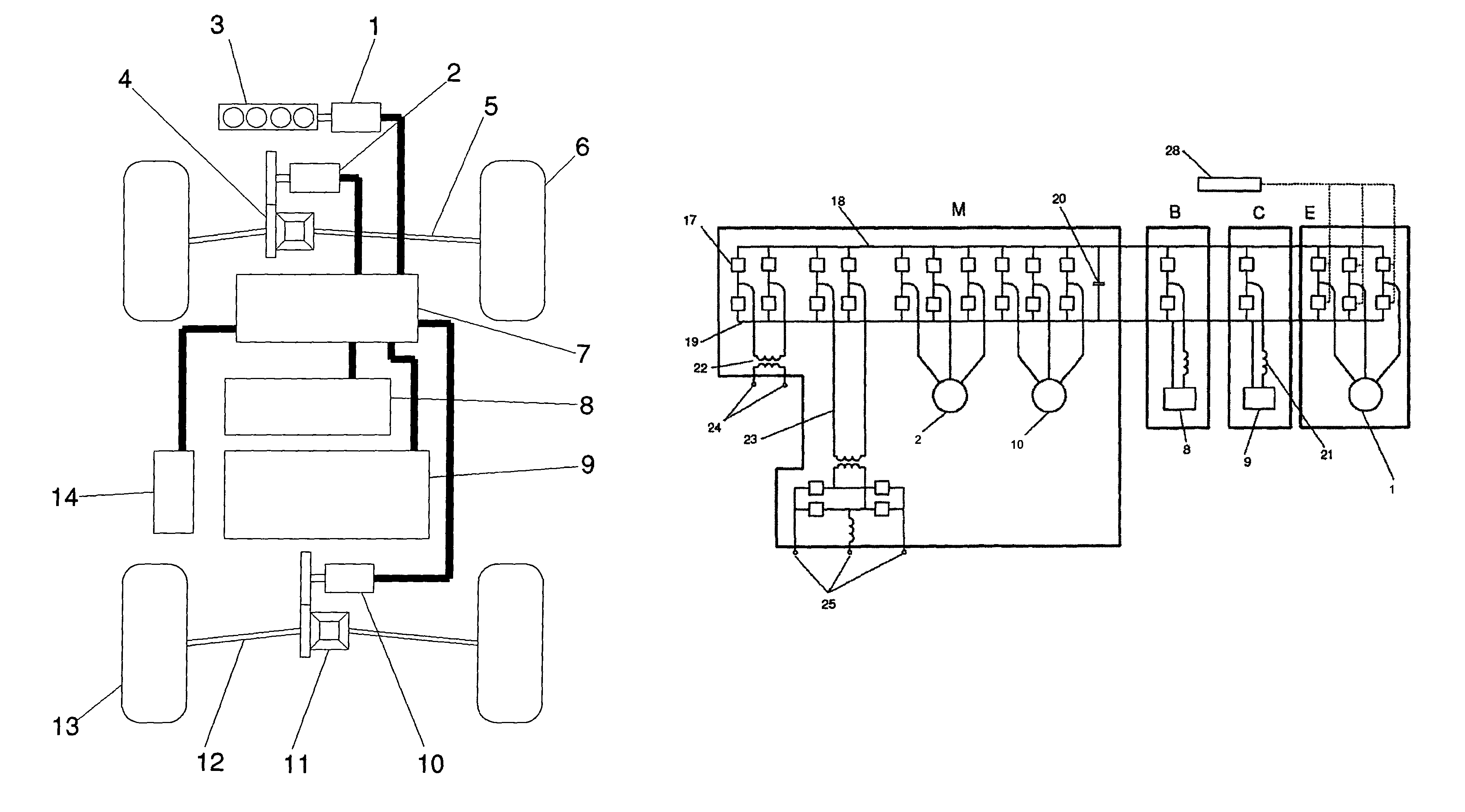
[0085]Referring to FIGS. 1-11, a preferred embodiment of the invention is disclosed. The power converter and controller 7 processes, conditions, and directs the flow of power between and among all of the connected devices. These include motors, generators, multiple energy storage device, a charger, and ancillary systems. The power converter and controller 7 sources or sinks DC, single phase AC, and multiple phase AC electricity over a range of voltage and power levels.

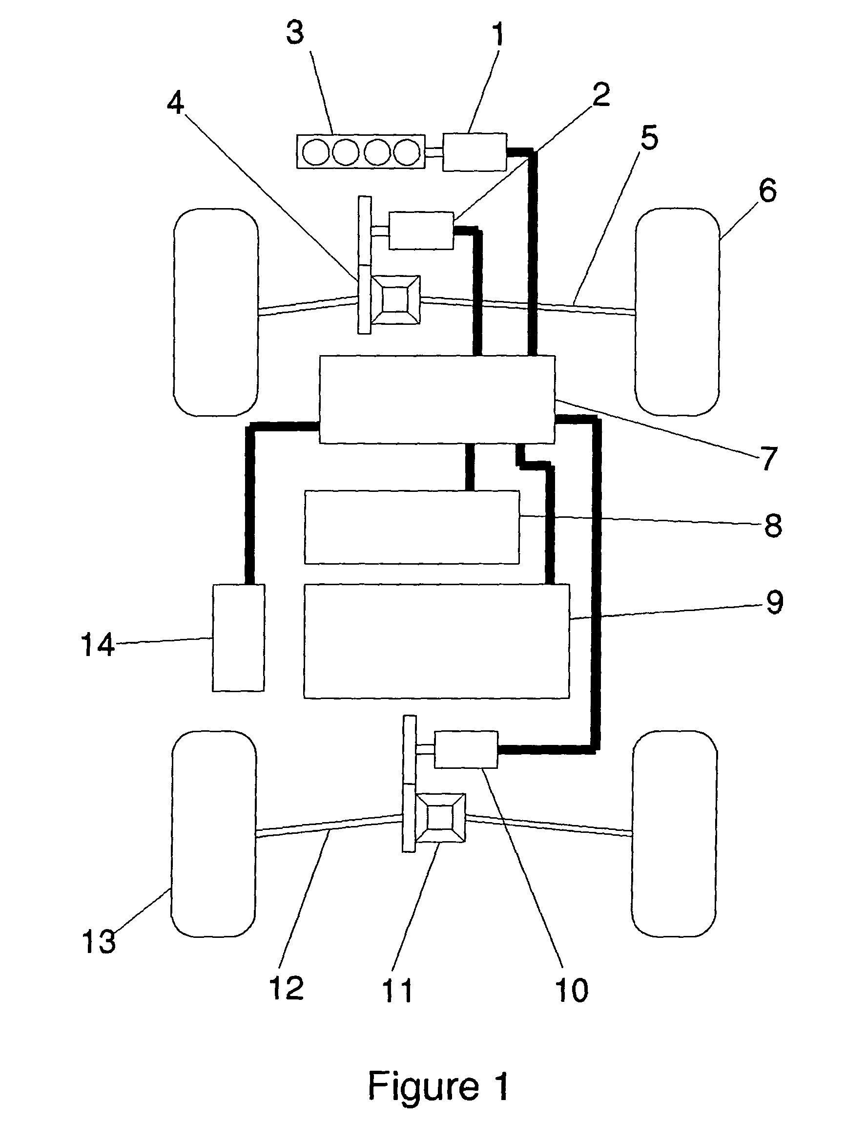
[0086]FIG. 1 shows a series hybrid propulsion system with front and rear wheel drive. This depiction is illustrative and not restrictive. The method disclosed herein may be applied to parallel and power split hybrids as well. Motive power is produced by the engine 3 that drives the first motor-generator 1. The battery 8 and fast energy storage system 9 store energy electrically. All of these devices are connected to the power electronics and control module 7 that delivers electricity to the front traction motor, MG22, ...


PUM


Abstract

A plug-in hybrid propulsion system includes a fast energy storage device that preserves battery life, where the energy storage elements of the hybrid drive train may be charged with externally supplied electricity as well as energy from the engine or regenerative braking. Electronic switches, passive electronics, an enclosure, controller circuitry, and / or control algorithms are used to manage the flow of power between a fuel powered engine, a battery, a fast energy storage system, traction motors; a charger, ancillary systems, an electrical distribution system, and / or a drive train.

Description

CROSS-REFERENCE TO RELATED APPLICATIONS[0001]This application claims priority to U.S. provisional application No. 60 / 596,443, entitled Power Converter and Controller for Plug-in Hybrid Propulsion with Fast Energy Storage, filed on Sep. 23, 2005; and to U.S. provisional application No. 60 / 596,909, entitled Method and Control for Plug-In Hybrid Propulsion with Fast Energy Storage, filed on Oct. 28, 2005.FIELD OF THE INVENTION[0002]This invention relates to plug-in hybrid propulsion systems for cars, trucks, and buses where the energy storage element of the hybrid drive train may be charged with externally supplied electricity as well as energy from the engine or regenerative braking.RELATED ART[0003]Existing products commonly found in the marketplace include conventional hybrid vehicles such as the Toyota Prius, Honda Insight, and Ford Escape Hybrid. More closely related to the present invention are prototype Daimler Chrysler Sprinter plug-in hybrid vans.[0004]The main problem with ex...

Claims


Application Information

Patent Timeline
Patent Type & Authority Patents(United States)
IPC IPC(8): B60K6/28B60K6/26B60K6/30B60K6/46B60K6/52B60L50/16
CPCB60K6/28B60K6/30B60K6/46B60K6/52B60L1/003B60L7/14B60L11/005B60L11/123B60L11/16B60L11/18B60W10/06B60W10/08B60W10/24B60W10/26B60W20/00B60K6/26B60K6/105Y10S903/907B60L2260/28Y02T10/6204Y02T10/6217Y02T10/6265Y02T10/6269Y02T10/6278Y02T10/6282Y02T10/6286Y02T10/7005Y02T10/7022Y02T10/7077Y02T90/14B60L50/40B60L50/61B60L50/30B60L50/60Y02T10/62Y02T10/70B60K2006/268B60W20/10Y02T10/7072
Inventor BENDER, DONALD ARTHUR
Owner AFS TRINITY POWER CORP
Why Eureka
Try Eureka