Wireless respiratory and heart rate monitoring system

a monitoring system and respiratory and heart rate technology, applied in the field of respiratory and heart rate monitoring systems, can solve the problems of system calibration, discontinuous monitoring of heart rate, and only usable current sensor designs, and achieve the effect of improving light transmission

Inactive Publication Date: 2010-06-22
SCIARRA MICHAEL
View PDF25 Cites 84 Cited by
  • Summary
  • Abstract
  • Description
  • Claims
  • Application Information

AI Technical Summary

Benefits of technology

[0014]Preferably, the barrier layer has a reflective surface facing the skin to reflect light radiation emitted from the light-emitting element. The sensor may further include a light guide for the light-emitting element to channel the light emitted from the light-emitting element through the skin and a light guide for each light-detecting element to channel the light reflected from beneath the skin. The light guides may include lens elements to focus the light radiation emitted to or from the skin, and reflective shields around each light guide to enhance light transmission therethrough.

Problems solved by technology

While there are accepted and practiced means that employ photo sensors to measure heart rate, current sensor designs have only been usable in highly perfused areas of the body that have underlying arterial blood supplies very close to the skin surface.
These locations also exhibit large motion artifacts when moving that can cause discontinuous monitoring of heart rate during the movement.
However, such systems require calibration, are cumbersome, and are wired to the remote monitor.
A single wraparound-type inductive coil or capacitive plate transducer generally cannot provide the required sensitivity due to the fact that the entire coil may move in response to artifact as well as respiratory efforts, which in some cases actually cancels or nullifies the desired respiratory movement detection.
Further, there is generally thought to be an incompatibility between locations on a subject's body for both heart and respiration sensors.
The sites that provide good photo sensor heart wave signals (fingers, wrist, ear and foot locations) are believed to be incompatible with sites for acquiring respiration signals (thoracic, umbilicus areas).

Method used


Image

  • Wireless respiratory and heart rate monitoring system
  • Wireless respiratory and heart rate monitoring system
  • Wireless respiratory and heart rate monitoring system

Examples


Embodiment Construction

)

[0027]In describing the preferred embodiment of the present invention, reference will be made herein to FIGS. 1-8 of the drawings in which like numerals refer to like features of the invention.

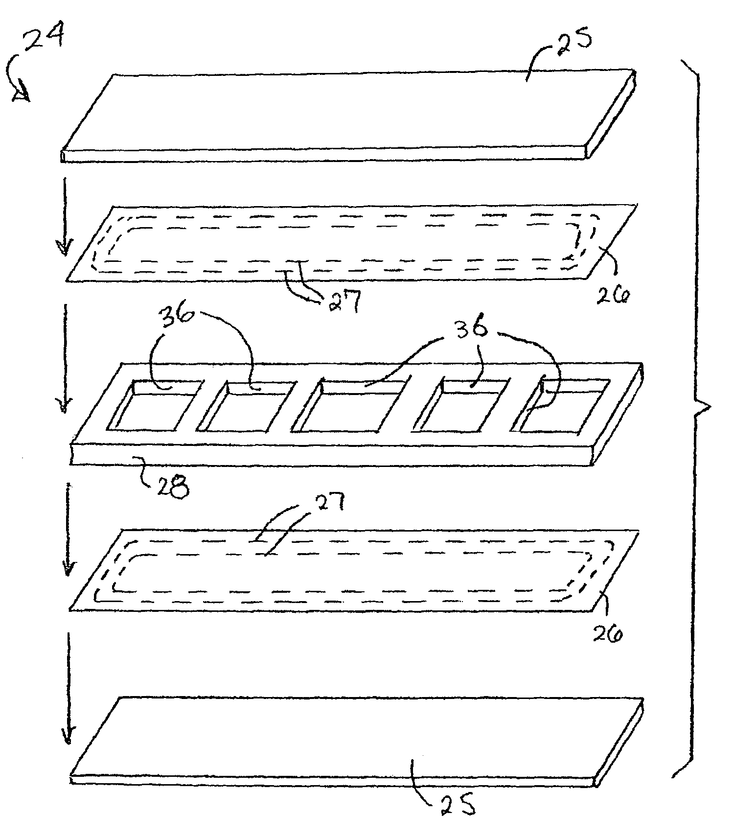
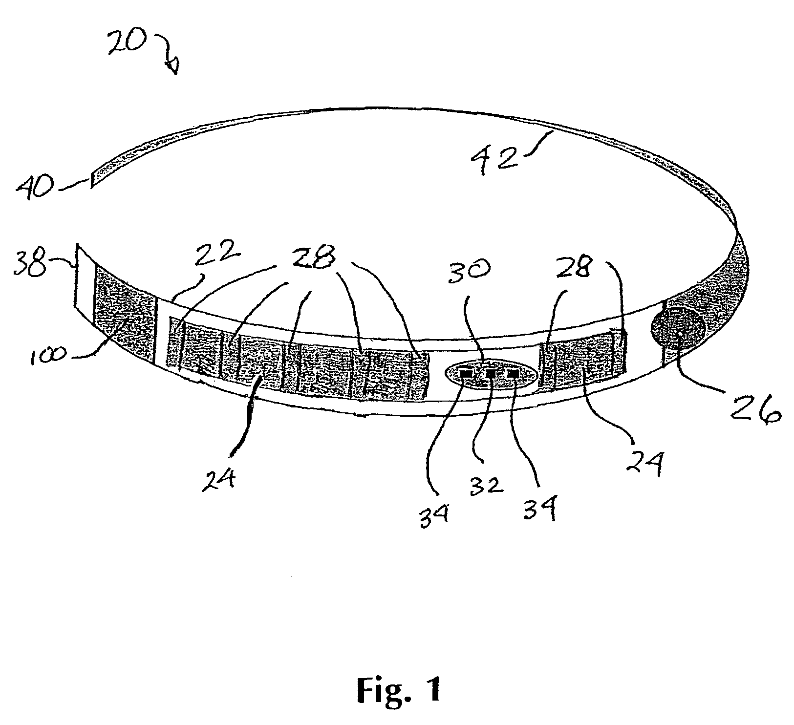
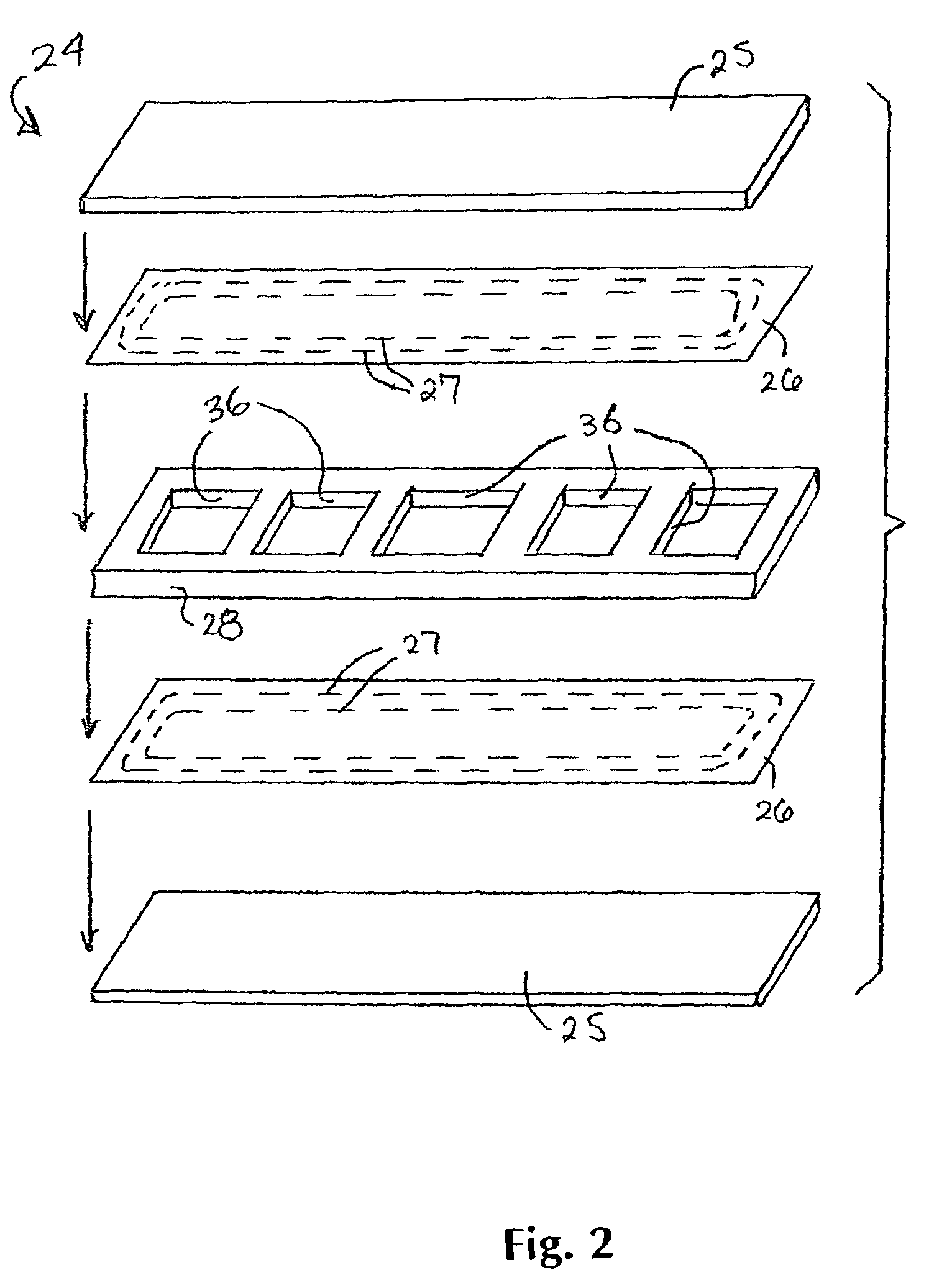
[0028]The present invention permits the wireless simultaneous physiological monitoring of both heart rate and respiration. This invention employs a sensor configuration that enables the monitoring of respiration with increased sensitivity and the monitoring of heart rate in areas of the body previously unsuitable for the acquisition of heart rate information. Additionally, the incorporation of the preferred heart rate sensor into an inductive plethmography respiration sensor provides for monitoring of the heart rate function at the optimum position for detecting respiration in infants, i.e., the umbilicus locations, since infants are for the most part “belly breathers”.

[0029]A preferred embodiment of the respiratory and heart monitor 20 of the present invention is depicted in FIG. 1. A compli...


PUM


Abstract

A combined respiratory and heart rate sensor for a mammal has a flexible support with a surface adapted to be positioned over the skin of a mammal. A pair of inductive coil or capacitive plate elements, spaced apart by a foam spacer having openings therein, are attached to the support surface and are capable of independently sensing respiratory movement of the mammal in a direction perpendicular to the support surface and producing an output signal proportional thereto. The heart rate sensor includes an LED attached to the flexible support capable, and at least two light-detecting elements spaced apart from the LED, each capable of independently sensing light radiation reflected through the skin and capillaries from the light-emitting element and producing an output signal proportional thereto. A barrier layer attached to the support shield from the light-detecting elements light radiation that is not emitted from the LED.

Description

BACKGROUND OF THE INVENTION[0001]1. Field of the Invention[0002]The present invention relates to a system and method for monitoring the respiratory and heart rate of infants and adults, as well as other mammals, and in particular to a monitoring system that may be applied to areas of the body previously thought to be unsuitable for such monitoring.[0003]2. Description of Related Art[0004]Heart rate monitors employing photo rather than electrode means to acquire heart rate offer the advantage of a noninvasive electrodeless method of monitoring subjects. While there are accepted and practiced means that employ photo sensors to measure heart rate, current sensor designs have only been usable in highly perfused areas of the body that have underlying arterial blood supplies very close to the skin surface. Heart rate monitoring sites have been restricted to appendages, for example, finger tips, wrist (ulner and radial arteries), ear lobes, toes and ankles. These locations also exhibit lar...

Claims


Application Information

Patent Timeline
Patent Type & Authority Patents(United States)
IPC IPC(8): A61B5/02A61B5/08
CPCA61B5/0205A61B5/6831A61B5/1135A61B5/02433A61B5/0002
Inventor SCIARRA, MICHAEL
Owner SCIARRA MICHAEL
Why Eureka
Try Eureka