

Dynamic upstream attenuation for ingress noise reduction
a technology of ingress noise and dynamic attenuation, which is applied in the field of dynamic upstream attenuation for ingress noise reduction, can solve the problems of one very common and troublesome source of ingress noise, and achieve the effect of reducing the presence of ingress noise and reducing the return of ingress nois
- Summary
- Abstract
- Description
- Claims
- Application Information
AI Technical Summary
Benefits of technology
Problems solved by technology
Method used
Image

Examples
example
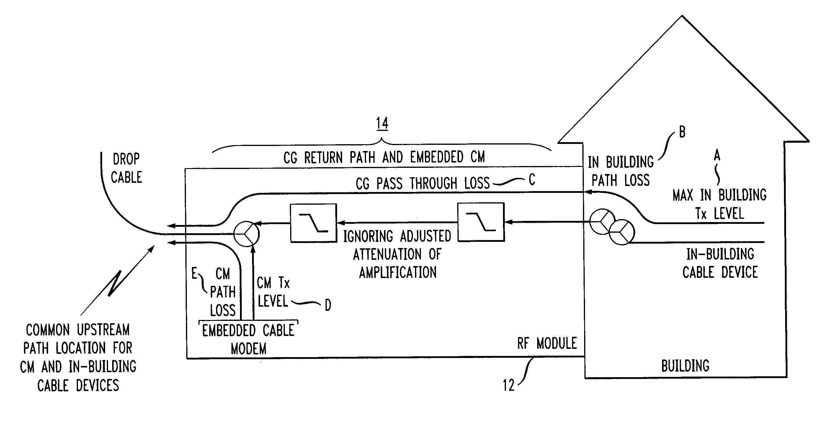
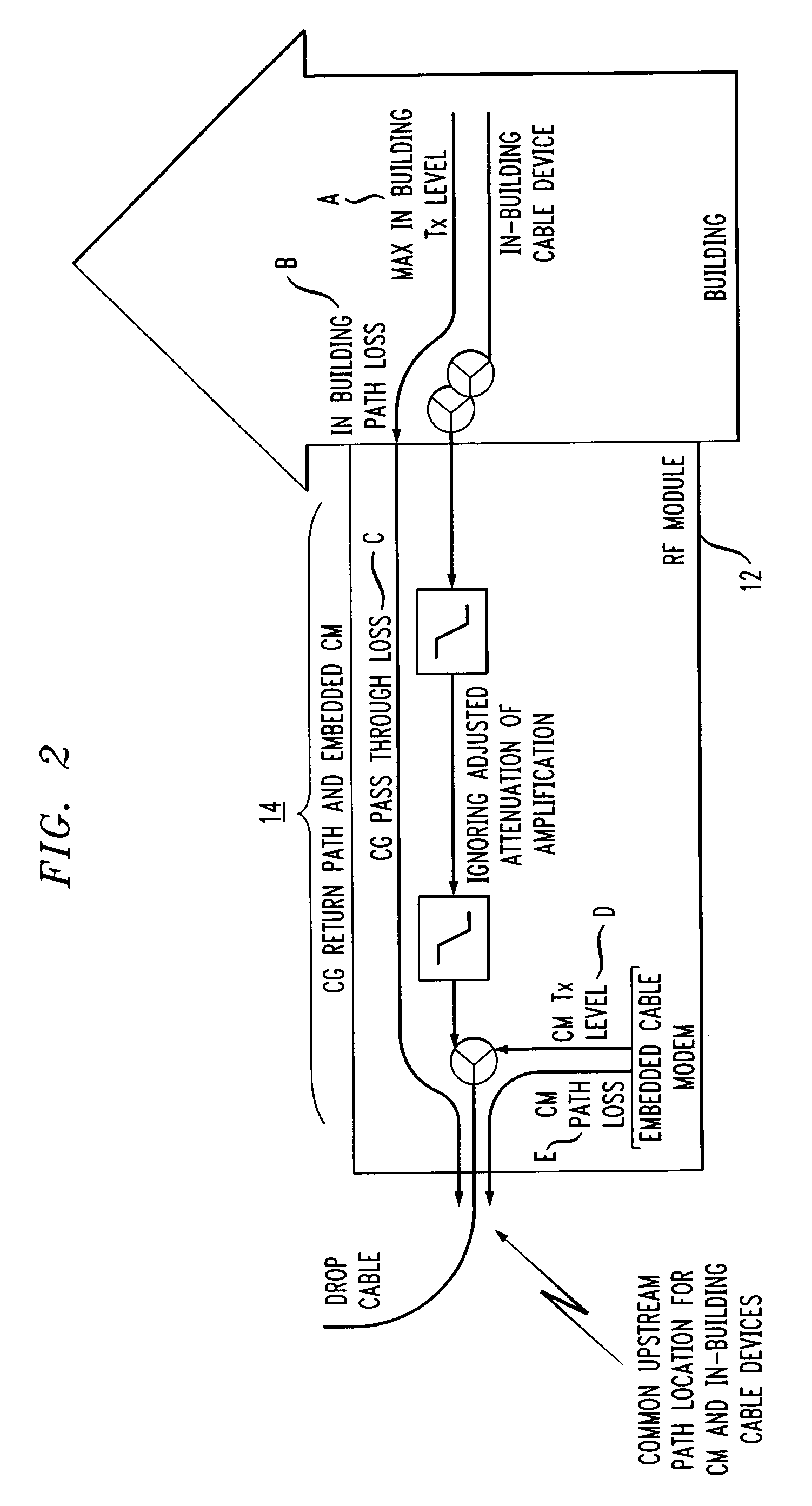
[0030]The following example is useful in understanding the application of the ingress noise reduction technique of the present invention. In particular, consider the following configured parameters for USLossCalc:[0031]MaxInBuildingTxLevel=58 dBmV for the maximum DOCSIS 1.1 transmit level for QPSK modulation. This could be associated with an individual cable modem, a video set-top-box, or telephony Media Terminal Adaptor (MTA) with embedded CM. Alternatively, the value could be smaller, associated with a narrowband video return path for a set-top-box that does not utilize an embedded CM. The choice of cable device associated with MaxInBuildingTxLevel will influence the choice of InBuildingTxBW, as shown below.[0032]InBuildingPathLoss=8 dB for two cable splitters in the home[0033]CGPassthroughLoss=5 dB for a single splitter and dual duplex filter losses between the CG's RF interface at the building and cable drop[0034]CMPathLoss=4 dB for a single splitter between the CG's CM interfac...
PUM
 Abstract
Description
Claims
Application Information