Structure of transmission for bicycle

a technology for bicycles and transmissions, applied in cycle equipments, gearing, hoisting equipments, etc., can solve the problems of increasing weight, affecting the stability of the transmission, and the derailleur shaft itself cannot be upsized, so as to improve the structure of the derailleur shaft mounting structur

Inactive Publication Date: 2010-06-29
HONDA MOTOR CO LTD
View PDF18 Cites 8 Cited by
  • Summary
  • Abstract
  • Description
  • Claims
  • Application Information

AI Technical Summary

Benefits of technology

[0008]It is an object of the present invention to solve such a problem, and to provide an improved structure of the derailleur shaft mounting structure in which the above-described problem is solved by exercising specific ingenuity in the derailleur shaft mounting structure.
[0009]The present invention, having solved the above-described problem, relates to an improved structure in a transmission for a bicycle in which mounting rigidity of the shaft is improved by employing a mounting structure in which the derailleur shaft is rigid. The shaft is, in a structure including a derailleur-type transmission fixed to a vehicle body, a structure of a transmission for a bicycle including a derailleur-type transmission being fixed to the vehicle body, wherein the transmission is disposed within a transmission case which can be divided into left and right halves, the left and right halves of the transmission case are provided with bosses coaxially projecting inwardly of the transmission case respectively, and the derailleur shaft of the transmission is supported by the left and right bosses. The left and right bosses are formed with holes therein, and the left and right halves of the transmission case are connected via a connecting member fitted to the holes.
[0011]In the present invention, in a structure including a derailleur-type transmission fixed to a vehicle body, since the transmission is disposed within a transmission case which can be divided into left and right halves, the left and right halves of the transmission case are provided with bosses coaxially projecting inwardly of the transmission case respectively. A derailleur shaft of the transmission is supported by the left and right bosses. The derailleur shaft can be supported from both sides and hence the mounting rigidity of the derailleur shaft is enhanced. In addition, the mounting of the shaft is stabilized, a necessity to increase the thickness of the derailleur shaft is eliminated and hence a lightweight shaft is achieved. Therefore, downsizing and weight reduction of the mounting structure of the derailleur shaft itself is achieved.
[0012]The stable state can be secured even when a deviated load is exerted during speed-change operation owing to the enhancement of rigidity of the mounting structure of the derailleur shaft. Therefore, operability during the speed-change operation can be improved. In addition, the connecting portion between the left and right halves of the transmission case can also be used as the supporting portion of the derailleur shaft.
[0013]In the present invention, the left and right bosses are formed with the holes therein. The connecting member fitted in the holes connects the left and right halves of the transmission case. Therefore, the left and right halves of the case are strongly connected to each other via both bosses with the connecting member fitted into the holes of the left and right bosses. The derailleur shaft is supported by both of the strongly connected bosses. The rigidity of the supporting portion is increased, and hence the derailleur shaft is supported in an extremely and strongly stable state irrespective of its simple supporting structure.
[0014]In the present invention, the derailleur shaft is disposed substantially at the same distance from a plurality of frame members extending from a head pipe of the vehicle body rearward and downward in side view. Therefore, the connecting member is located at the position where connecting rigidity between the left and right halves of the transmission case is required. In view of this, the connecting member can also be used for supporting the derailleur shaft while securing case rigidity, and cost reduction can be achieved.

Problems solved by technology

According to the cantilever supporting structure of the derailleur (shifting frame) as disclosed in the above document, sufficient rigidity of the derailleur shaft (movable member) is difficult to secure.
However, when such a countermeasure is taken, increase in weight is inevitable, whereby upsizing of the derailleur shaft mounting structure itself cannot be avoided.

Method used


Image

  • Structure of transmission for bicycle
  • Structure of transmission for bicycle
  • Structure of transmission for bicycle

Examples


Embodiment Construction

[0038]Referring now to FIGS. 1 to 18, embodiments of a structure of a transmission for a bicycle provided with a derailleur according to the present invention will be described.

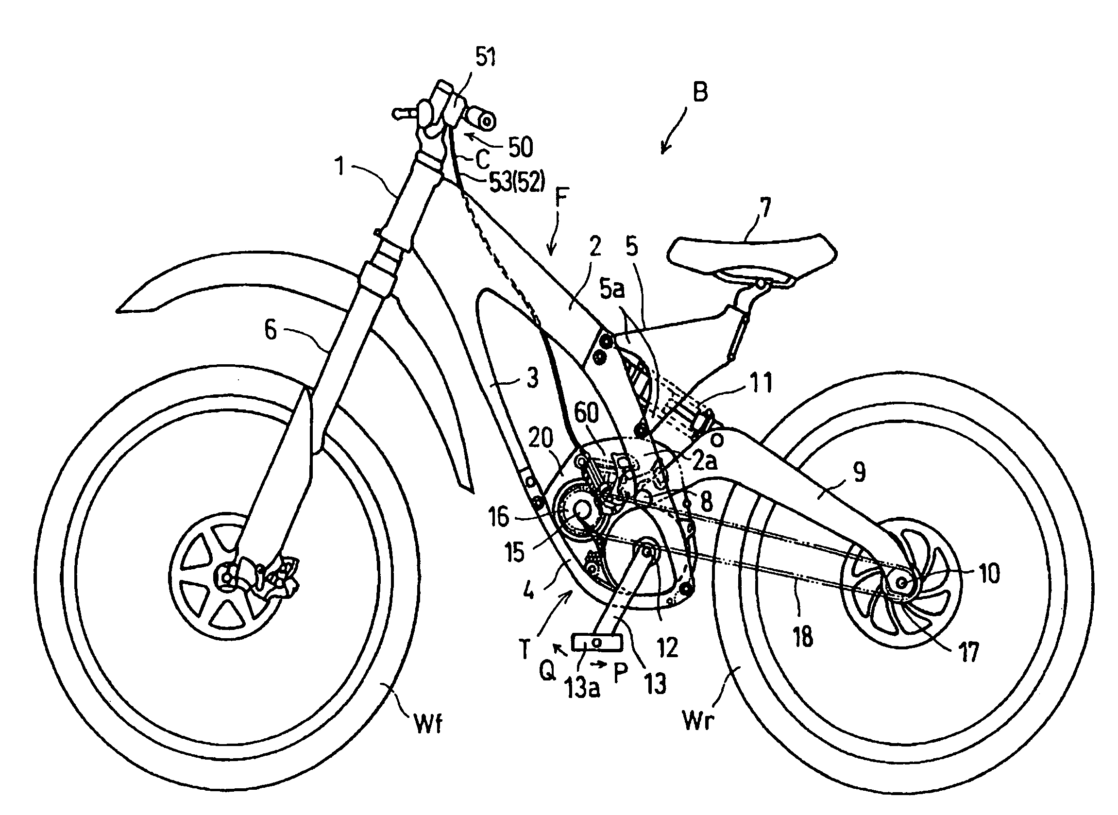
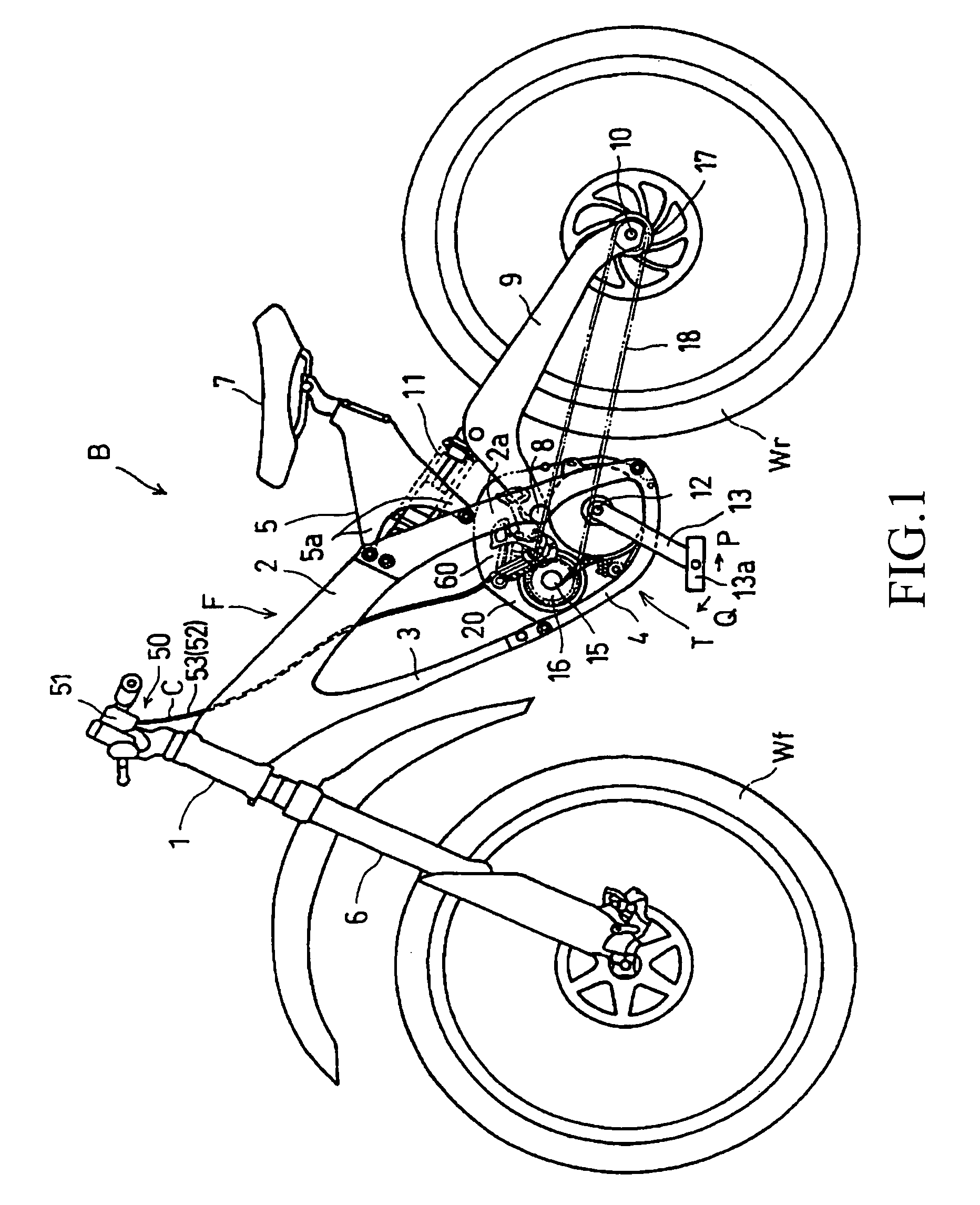
[0039]FIG. 1 is a left side view of a bicycle B in which a transmission T having a derailleur is used according to the present invention.

[0040]The bicycle B is a downhill bicycle, and is used, for example, for competitive sports that are timed for running down a dirt course, such as a forest road provided with a high-speed corner or a jumping section.

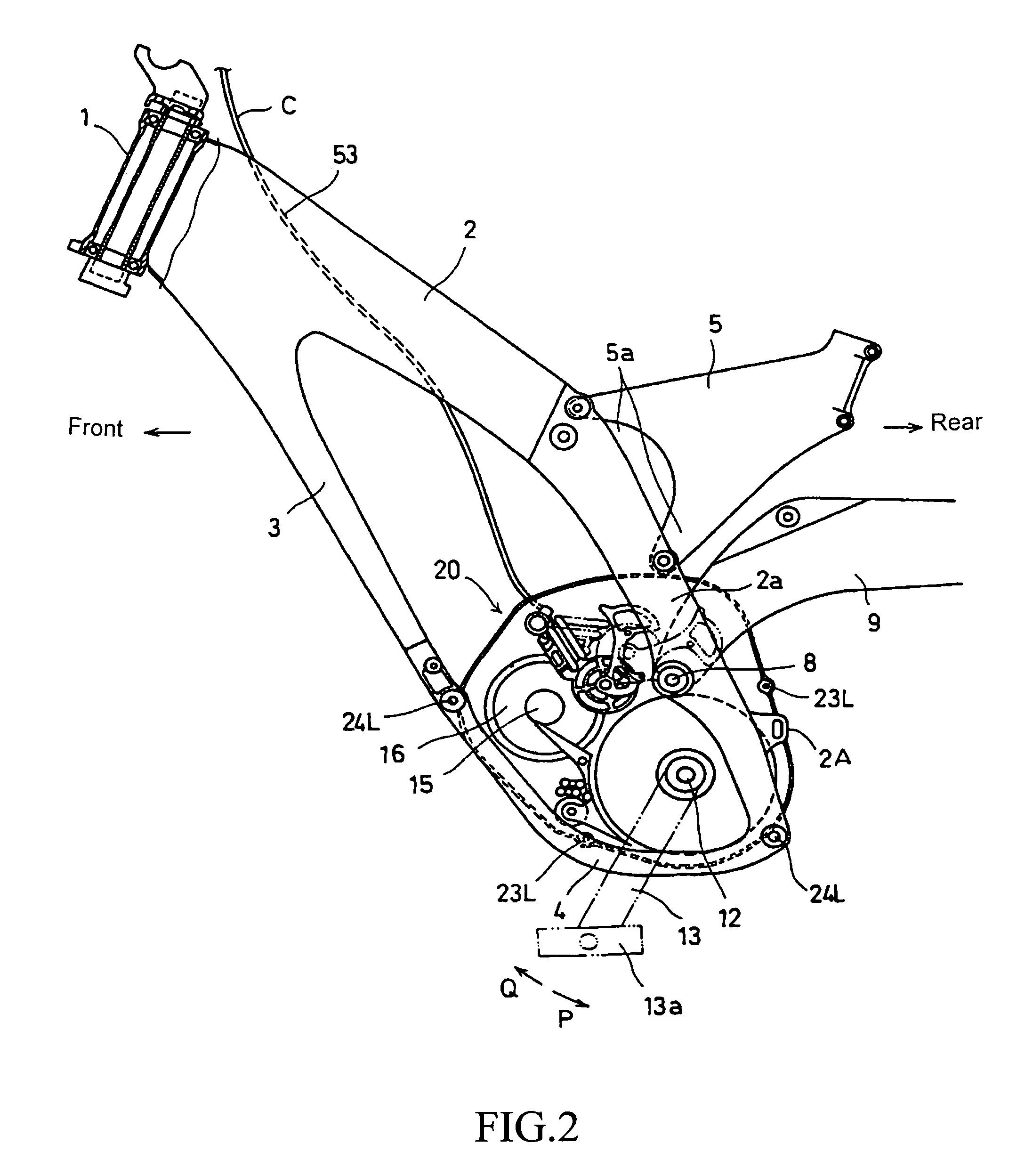
[0041]A vehicle body frame F of the bicycle B includes, as shown in FIGS. 1 and 2, a pair of left and right mainframes 2 extending from a head pipe 1 rearward and obliquely downward. A down tube 3 extends from the front lower ends of both mainframes 2 rearward and obliquely downward. The lower ends of a pair of the mainframes 2 and the lower end of the down tube 3 are connected to each other via an under tube 4. A saddle frame 5 is provided so as to extend rearwa...


PUM


Abstract

To achieve downsizing and weight reduction of a derailleur shaft and the mounting structure thereof and to improve the rigidity of the derailleur shaft without increasing the thickness thereof more than necessary. A transmission case is divided into left and right halves, and the left and right halves are provided with bosses therein having holes opposing each other. The bosses are brought into abutment with each other and united by fitting tightening bolts to the holes of the bosses and tightening the same. A sleeve-shaped derailleur shaft is fitted on the outer periphery of the bosses to support and mount the derailleur shaft. The derailleur shaft includes a hole at the shaft end thereof. A mounting position of the derailleur shaft is achieved by a pin inserted into the hole and a hole provided on one of the cases.

Description

CROSS-REFERENCE TO RELATED APPLICATIONS[0001]This non-provisional application claims priority under 35 U.S.C. §119(a) on Patent Application No. 2004-068101, filed in Japan on Feb. 10, 2004, the entirety of which is incorporated herein by reference.BACKGROUND OF THE INVENTION[0002]1. Field of the Invention[0003]The present invention relates to a structure of a transmission for a bicycle including a derailleur. In particular, the present invention relates to an improved structure of a transmission for a bicycle characterized by the mounting structure of the derailleur in the transmission.[0004]2. Description of Related Art[0005]In the related art, a transmission for a bicycle provided with a derailleur is known. The derailleur has a supporting arm with a pantograph mechanism, which is adapted to shift a power transmission chain wound around a multi-stage sprocket wheel supported by a rear wheel hub and mounted to the rear wheel hub via a shaft step-by-step is known. The derailleur is ...

Claims


Application Information

Patent Timeline
Patent Type & Authority Patents(United States)
IPC IPC(8): F16H61/00B62M25/00B62J13/00B62M9/121B62M9/124B62M9/1242B62M9/125B62M9/128B62M9/131B62M11/14F16H57/021
CPCB62M11/145B62M9/121
Inventor MATSUMOTO, SHINYAIGUCHI, KAZUNARI
Owner HONDA MOTOR CO LTD
Why Eureka
Try Eureka