What is disadvantageous is the high level of power dissipation of conventional transformers which arises here, as well as the structural height of conventional electromagnetic transformers, which is several millimeters and is a factor of interference for small powers of up to about 100 Watts, but in particular up to 10 Watts.
In addition, the technological basic expense for constructing integrated magnetics in the power range below about 50 Watts is clearly too high in comparison with a discretely structured circuit.
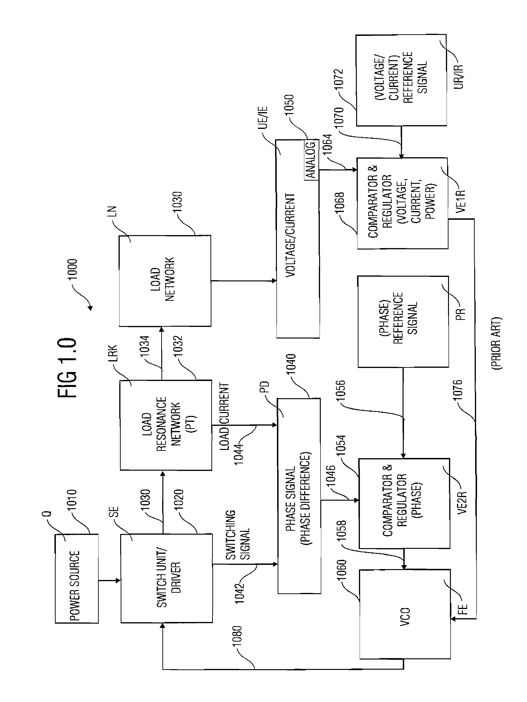
However, a
disadvantage of this configuration is that even though the power present at a load fed with
alternating current may be regulated via this phase shaft and / or
phase difference, the load-circuit elements L and C must be known with a relatively high level of precision for a certain power to be set.
If, however, the value of L is not known, the power cannot be adjusted in an exact manner.
Thus, two
feedback circuits are required which also do not achieve galvanic separation between input and output.
However, in addition to a
phase detector, which compares the phase between a switch voltage and a load current, a rectifying circuit is also used, which resistively loads the tapping of the load (sense
resistor), and which would thus corrupt the
signal of the
load circuit if one wanted to couple out, or extract, or tap, this phase
signal from the piezo
transformer itself.
Therefore, one cannot achieve galvanic separation between the load and the input without using an additional optocoupler or another galvanically separating
coupling circuit, which is also not required in the application set forth in the document mentioned.
However, by doing this, a current from the transformation network of the PT is not included in the regulation, so that a galvanic separation of this circuit without galvanically separating feedback elements is not possible, since a output quantity, or variable, is always required for regulation (frequency and
duty cycle).
This circuit is also not suitable for galvanic separation without feeding-back elements from the output to the input.
This configuration, however, entails major disadvantages.
In this case, the output voltage is not so easy to regulate in a dynamic manner.
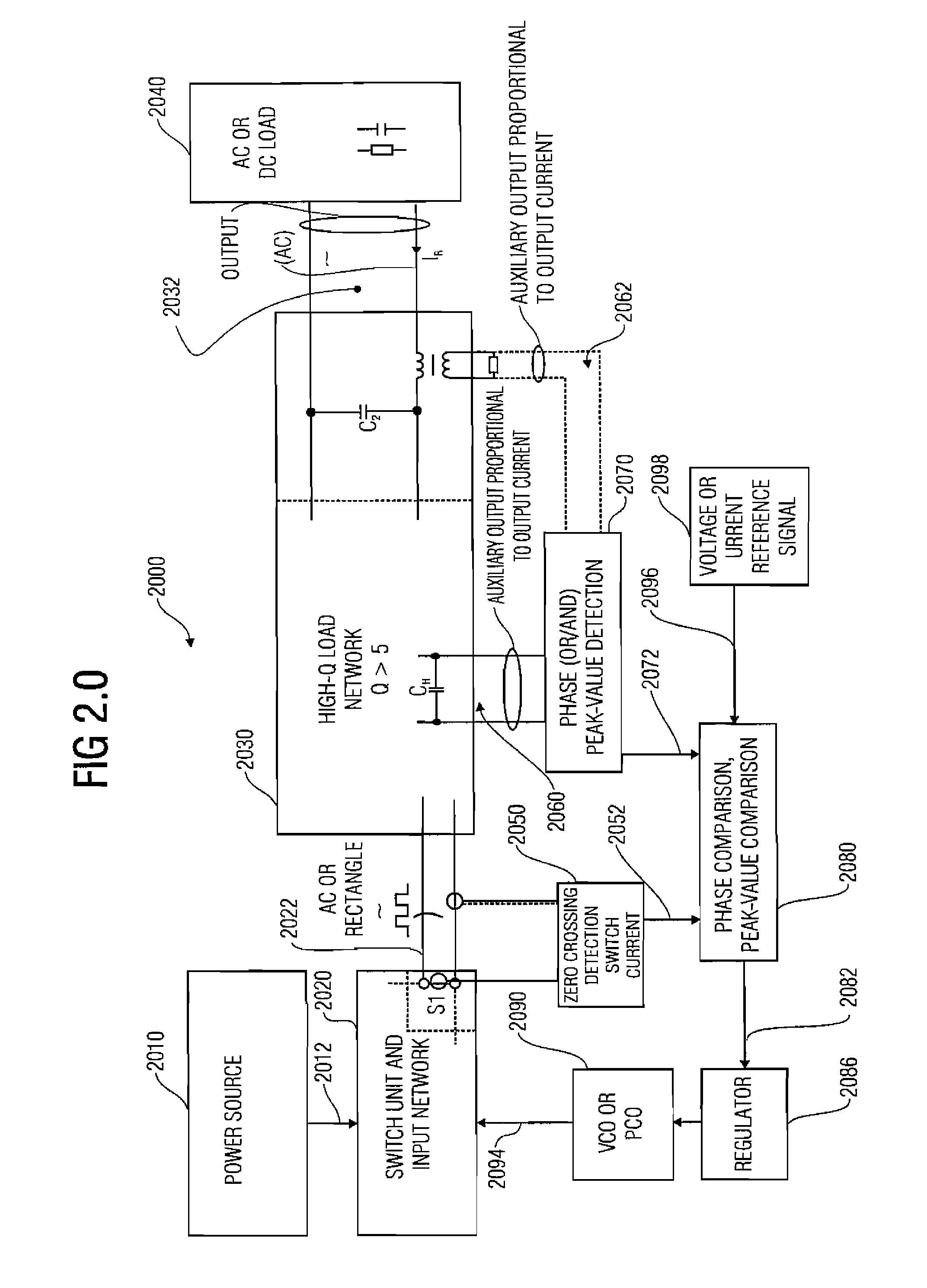
However, what is disadvantageous is that it is necessary to generate the load current from an additional device which acts as a transformer and is not already included in the
load circuit.
With downward-transforming applications, however, a loading at the auxiliary output by a
resistive load or a rectification is problematic, since one would have to keep the voltage at a correspondingly low level to realize low-loss tapping.
Consequently, however, the signal-to-
noise ratio is too small to be able to evaluate the auxiliary signal in a reliable manner.
If, however, the input voltage is also changed on a large scale, the publication mentioned offers no satisfying solution.
In addition, it is not possible to detect, via the phase signal of the output or of the auxiliary output which has thus been generated, whether zero-voltage switching (ZVS) is still possible, or whether, for example with a small load and a
high input voltage, the relative turn-on time approaches zero, so that
continuous operation is no longer possible, and so that one would have to switch to burst mode.
So far, there have been no fundamental technical solutions and suggestions for this which enable operation of various topologies of a load resonance converter using one and the same
control principle.
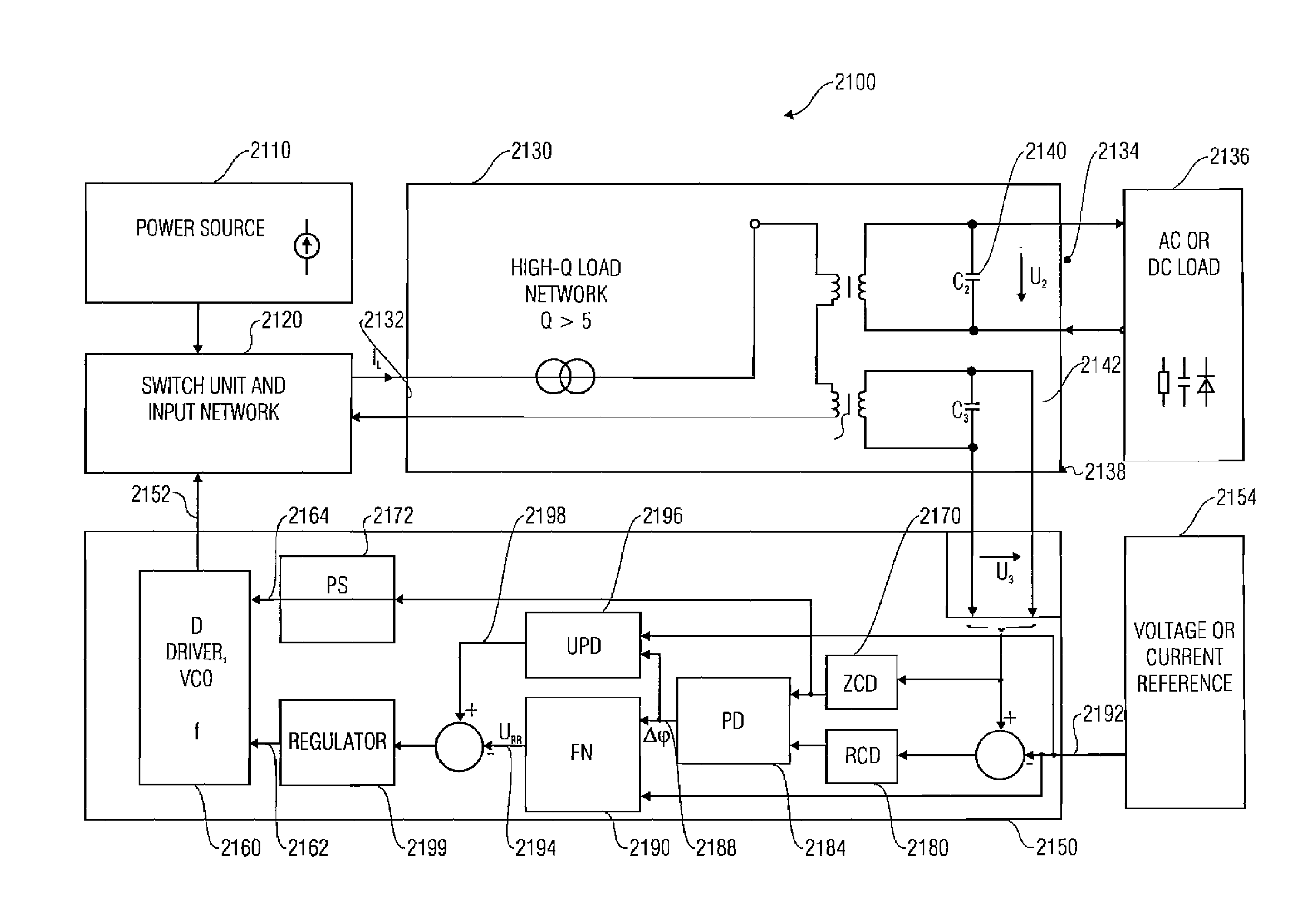
In addition, there has so far been no useful technical solution to using a
load circuit at the same time for supplying the
control circuit when no additional auxiliary tappings are to be provided for supplying the
control power and when, at the same time, the load current is not to be corrupted by such an auxiliary current supply with regard to its detection in terms of amplitude and phase position.
Furthermore, there has so far been no technical solution to detecting a variable proportional to the output voltage, in a manner in which it is galvanically separate from the output, such that it is neither electrically connected to a potential of the output voltage nor to a potential of the input voltage at the same time, but may be evaluated at any electrical potential desired, so that the two input electrodes may be guided via a voltage supply circuit, connected upstream from the piezo transformer, for supplying the control circuit, rather than also having to be connected, for example, at the reference potential of the control circuit, which is required for evaluating this auxiliary voltage proportional to an output voltage, the detection being irrespective of whether the output voltage is a pure alternating voltage or a trapezoid or oblong alternating voltage which acts toward the load via a rectifying circuit, and the amplitude of which corresponds to the direct load voltage.

