Method for manufacturing rigid internal gear of wave gear device

a technology of wave gear and internal gear, which is applied in the direction of gear, transportation and packaging, other domestic objects, etc., can solve the problems of compromising the advantage of a lightweight flexible meshing type gear device, the weight is considerable, and the wave gear device has few components. , to achieve the effect of high durability

Active Publication Date: 2010-07-06
HARMONIC DRIVE SYST IND CO LTD +1
View PDF14 Cites 16 Cited by
  • Summary
  • Abstract
  • Description
  • Claims
  • Application Information

AI Technical Summary

Benefits of technology

[0008]A main object of the present invention is to provide a method for manufacturing a rigid internal gear in which an internally toothed portion formed with internal teeth is formed from a strong material with high abrasion resistance, in which a gear main body portion is formed with lightweight materials, and in which these portions can be securely integrated, and to provide a rigid internal gear manufactured with this method.
[0027]In the rigid internal gear produced by the method of the present invention, the gear main body portion and the internally toothed portion are securely integrated by powder forging. Therefore, both portions are not required to be integrated using bolts or the like, and a lightweight rigid internal gear with high durability can therefore be obtained.
[0047]In the rigid internal gear produced by the method of the present invention, the gear main body portion and the internally toothed portion are securely integrated by hot extrusion. Both portions are not therefore required to be integrated using bolts or the like, and a lightweight rigid internal gear with high durability can be obtained.

Problems solved by technology

The wave gear device has few components and is lightweight in comparison with other forms of reduction gears.
In particular, when the rigid internal gear is integrally formed with a mounting flange for mounting on the motor or an output-side member, or when a housing is integrally formed, the weight is considerable, and the advantage of a lightweight flexible meshing type gear device is compromised.

Method used


Image

  • Method for manufacturing rigid internal gear of wave gear device
  • Method for manufacturing rigid internal gear of wave gear device
  • Method for manufacturing rigid internal gear of wave gear device

Examples


Embodiment Construction

[0051]The present invention will be described in detail below with reference to the drawings.

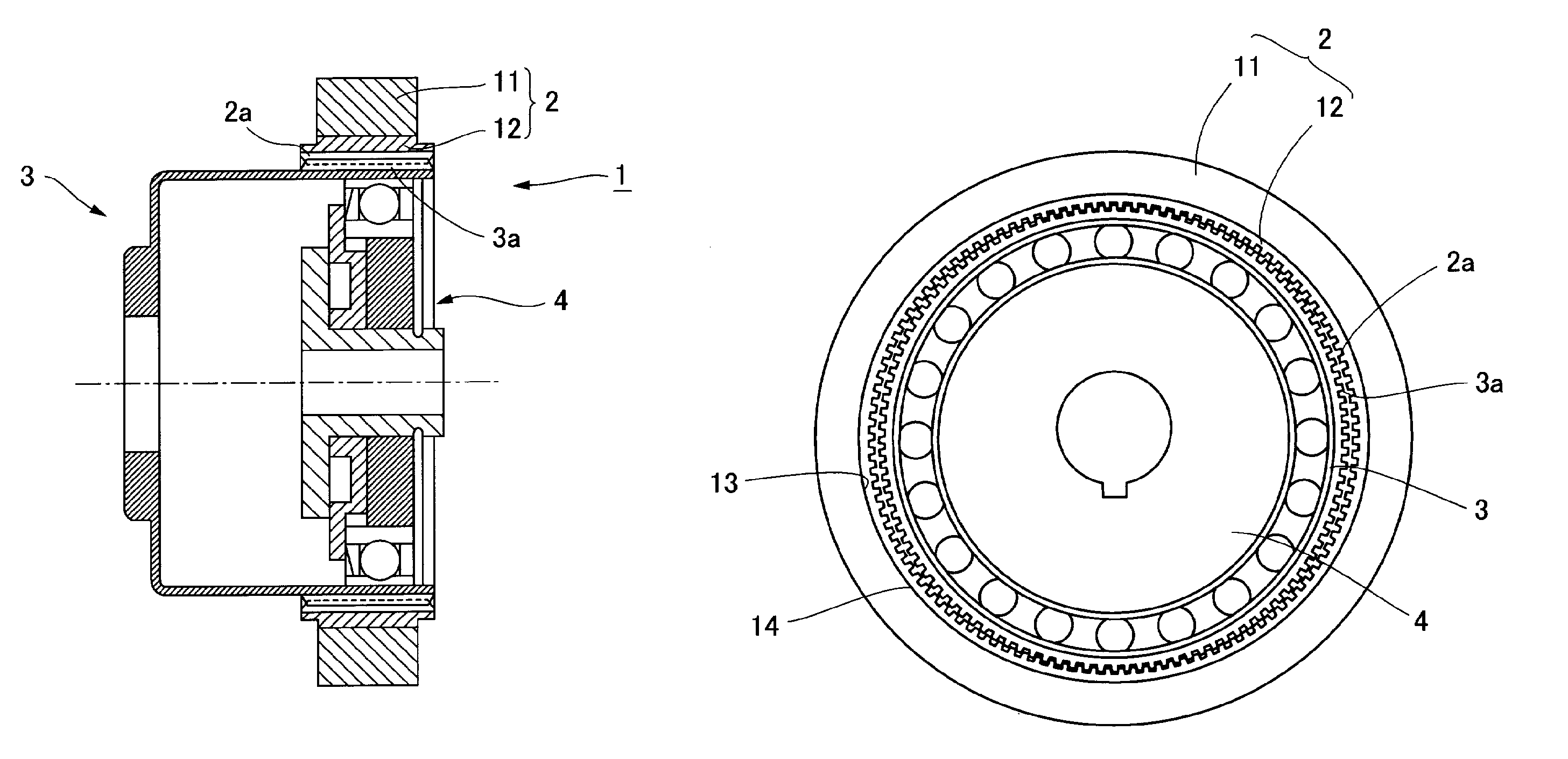
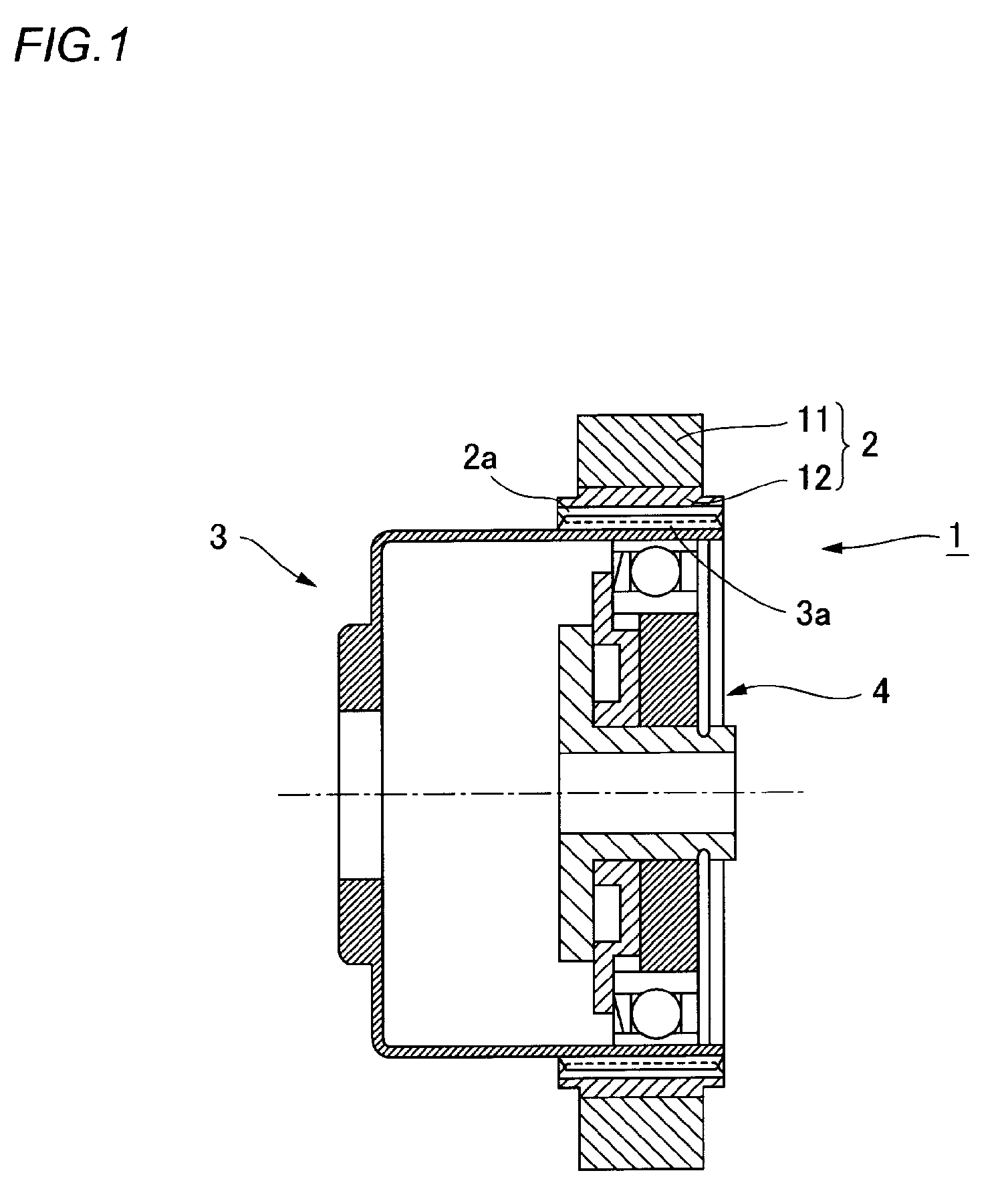
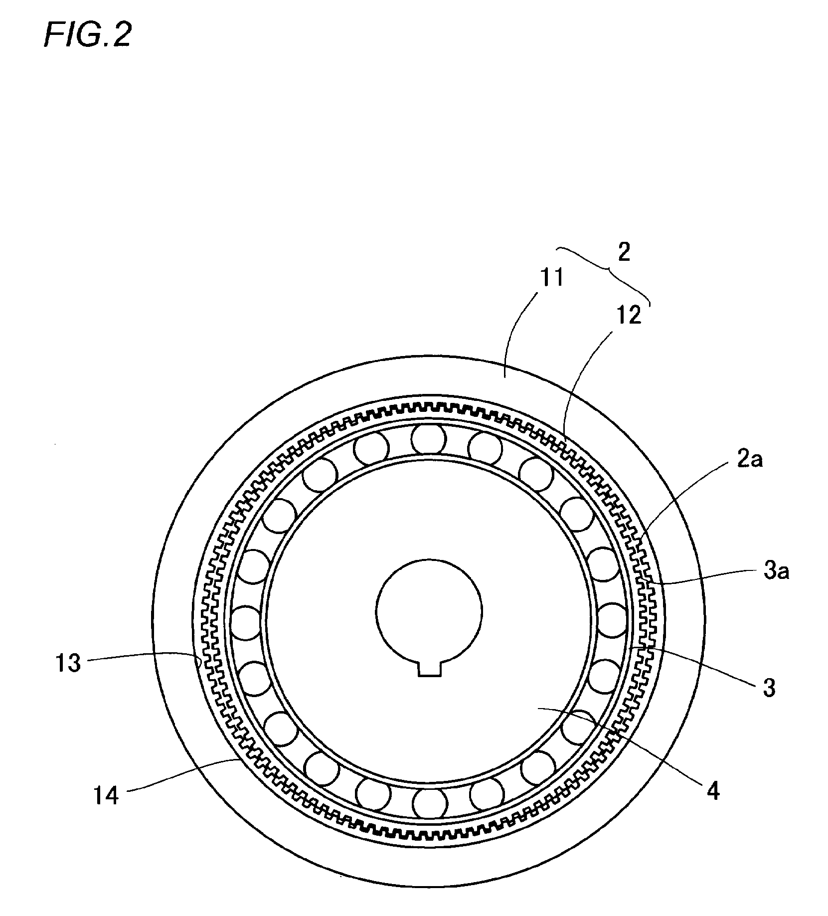
[0052]FIG. 1 is a schematic cross-sectional view showing a wave gear device, and FIG. 2 is a schematic front view thereof. As shown in the drawings, a wave gear device 1 is comprised of an annular rigid internal gear 2, a cup-shaped flexible external gear 3 disposed inside thereof, and a wave generator 4 fitted therein. The wave generator 4 is elliptically contoured and the flexible external gear 3 is elliptically flexed, causing external teeth 3a to partially mesh with internal teeth 4a at both ends of a major axis of the ellipsis. When the wave generator 4 is rotatably driven by a motor or another high speed rotating drive source, the meshing locations of the gears 2 and 3 move circumferentially. The difference in the number of teeth of the gears 2 and 3 is usually two, and relative rotational movement is produced between the gears 2 and 3 due to the difference in the number of teeth. Usua...


PUM

PropertyMeasurementUnit
abrasion resistanceaaaaaaaaaa
flexibleaaaaaaaaaa
weightaaaaaaaaaa

Abstract

The present invention provides a method for manufacturing a rigid internal gear for a wave gear device comprising an internally toothed portion and a gear main body portion comprised of different materials. In this method, a gear main body ring for forming a gear main body portion is preformed using a first aluminum alloy powder; an internal teeth-forming ring is preformed using a second aluminum alloy powder that has lower processability, is less durable, has higher abrasion resistance, and is harder than the first aluminum alloy powder; the internal teeth-forming ring is fitted inside the gear main body ring and the assembly is integrated by powder forging; and the resulting ring-shaped forging is subjected to post-processing, including cutting teeth. The gear main body portion and internally toothed portion are securely integrated by powder forging, and a lightweight rigid internal gear with high durability can therefore be obtained.

Description

BACKGROUND OF THE INVENTION[0001]1. Field of the Invention[0002]The present invention relates to a method for manufacturing a rigid internal gear of a wave gear device in which an internally toothed portion formed with internal teeth and a gear main body are securely joined and integrated.[0003]2. Description of the Related Art[0004]A wave gear device commonly has an annular rigid internal gear, a flexible external gear disposed on an inner side thereof, and a wave generator fitted inside the flexible external gear. The wave generator is commonly elliptically contoured, the flexible external gear is elliptically flexed by the wave generator, and external teeth formed on an external peripheral surface thereof partially mesh with internal teeth of the rigid internal gear. When the wave generator is rotated by a motor or the like, the meshing locations of the two gears move circumferentially. Since there is a difference in the number of external and internal teeth, relative rotational ...

Claims


Application Information

Patent Timeline
Patent Type & Authority Patents(United States)
IPC IPC(8): B21K1/30F16H1/28F16H49/00
CPCF16H49/001Y10T29/49462Y10T29/49476Y10T29/49474Y10T74/19Y10T29/49467
Inventor KOBAYASHI, MASARUKAJI, TOSHIHIKO
Owner HARMONIC DRIVE SYST IND CO LTD
Why Eureka
Try Eureka