Coaxial cable

a coaxial cable and carbon nanotube technology, applied in the direction of power cables, cables, insulated conductors, etc., can solve the problems of carbon nanotubes in the prior art conducting wires arranged disorderly, signal decay during transmission, and the above-mentioned skin effect has not been eliminated

Active Publication Date: 2010-07-06
ABBOTT CARDIOVASCULAR +2
View PDF13 Cites 73 Cited by
  • Summary
  • Abstract
  • Description
  • Claims
  • Application Information

AI Technical Summary

Benefits of technology

[0005]Coaxial cables are used as carriers to transfer electrical power and signals. A conventional coaxial cable includes a core, an insulating layer outside the core, and a shielding layer outside the insulating layer, usually surrounded by a sheathing layer. The core includes at least one conducting wire. The conducting wire can be a solid or braided wire, and the shielding layer can, for example, be a wound foil, a woven tape, or a braid. However, as for the conducting wire made of a metal, a skin effect will occur in the conducting wire, thus the effective resistance of the cable becomes larger, and causes signal decay during transmission. Further, the conducting wire and the shielding layer made of metal has less strength for its size, so must be comparatively greater in weight and diameter, and thus in use.

Problems solved by technology

However, as for the conducting wire made of a metal, a skin effect will occur in the conducting wire, thus the effective resistance of the cable becomes larger, and causes signal decay during transmission.
However, the carbon nanotubes in the conducting wire of the prior art are arranged disorderly.
Thus, the above-mentioned skin effect has still not been eliminated in coaxial cables employing carbon nanotubes.

Method used


Image

  • Coaxial cable
  • Coaxial cable
  • Coaxial cable

Examples


Embodiment Construction

[0022]References will now be made to the drawings to describe, in detail, embodiments of the present coaxial cable and method for making the same.

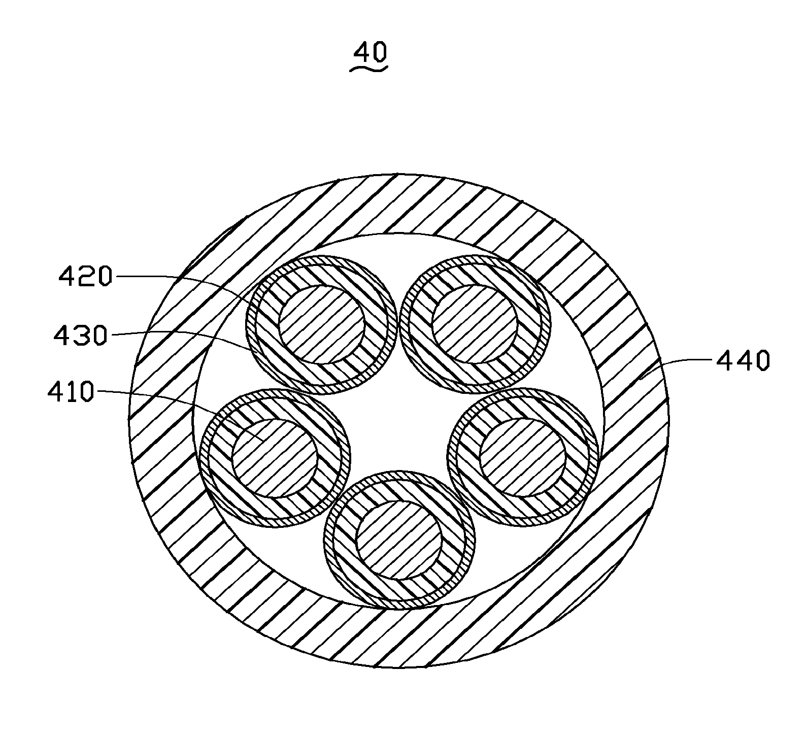
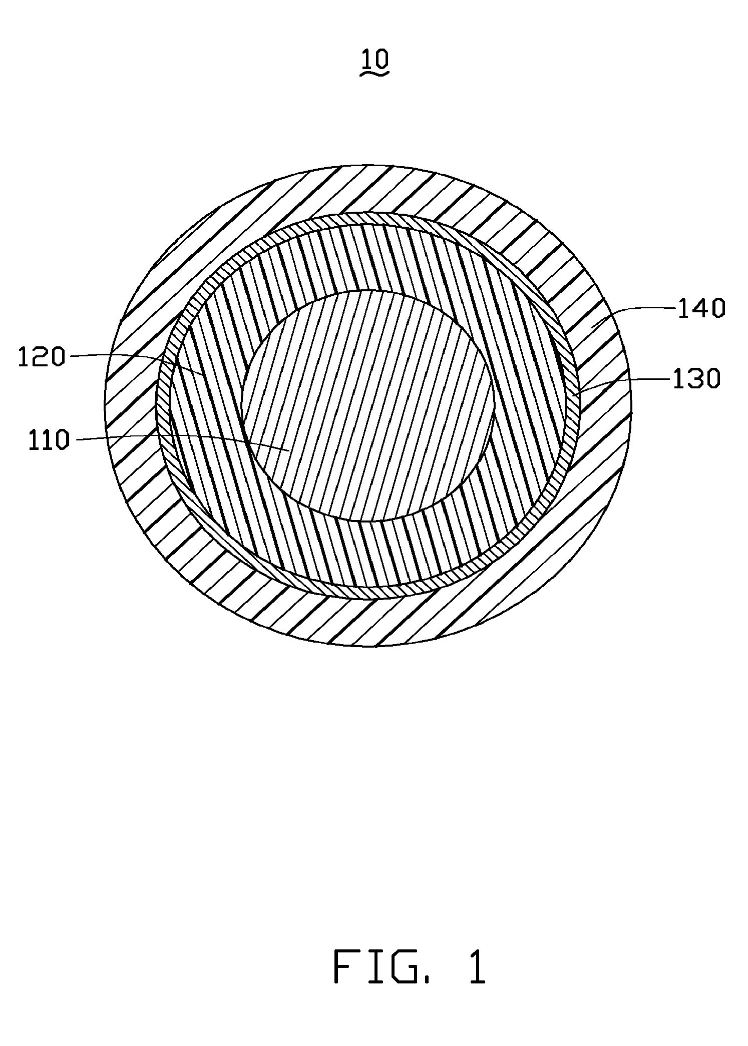
[0023]Referring to FIG. 1, a coaxial cable 10 according to a first embodiment includes a core 110, an insulating layer 120 wrapping the outer circumferential surface of the core 110, a shielding layer 130 surrounding the outer circumferential surface of the insulating layer 120, and a sheathing layer 140 covering the outer circumferential surface of the shielding layer 130. The core 110, the insulating layer 120, the shielding layer 130, and the sheathing layer 140 are coaxial.

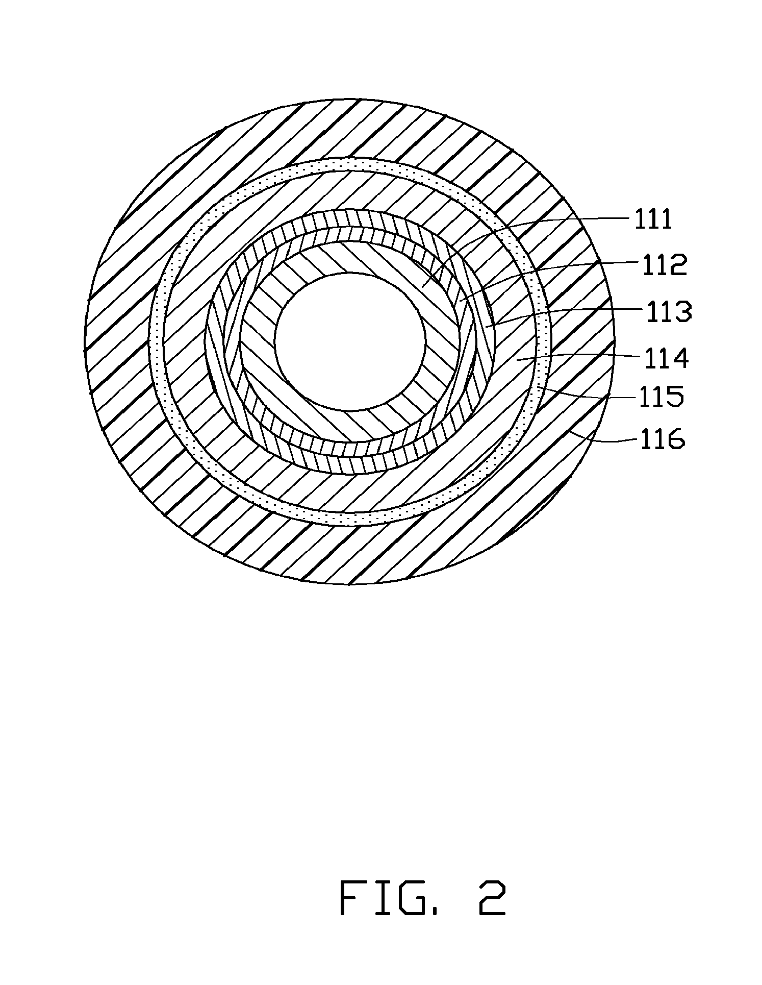
[0024]The core 110 has at least one carbon nanotube wire-like structure. Specifically, the core 110 includes a single carbon nanotube wire-like structure or a plurality of carbon nanotube wire-like structures. In the present embodiment, the core 110 includes one carbon nanotube wire-like structure. A diameter of the carbon nanotube wire-like structure can range from ...


PUM

PropertyMeasurementUnit
diameteraaaaaaaaaa
thicknessaaaaaaaaaa
diameteraaaaaaaaaa

Abstract

A coaxial cable includes a core, an insulating layer, a shielding layer, a sheathing layer. The core includes an amount of carbon nanotubes having at least one conductive coating disposed about the carbon nanotubes. The carbon nanotubes are orderly arranged. The insulating layer is about the core. The shielding layer is about the insulating layer. The sheathing layer is about the shielding layer.

Description

RELATED APPLICATIONS[0001]This application claims all benefits accruing under 35 U.S.C. §119 from China Patent Application No. 200810066046.8, filed on 2008 Feb. 1 in the China Intellectual Property Office, the disclosure of which is incorporated herein by reference. This application is related to commonly-assigned, applications entitled, “METHOD FOR MAKING COAXIAL CABLE”, Ser. No. 12 / 321,573, filed Jan. 22, 2009; “INDIVIDUALLY COATED CARBON NANOTUBE WIRE-LIKE STRUCTURE”, Ser. No. 12 / 321,568, filed Jan. 22, 2009; “METHOD FOR MAKING INDIVIDUALLY COATED AND TWISTED CARBON NANOTUBE WIRE-LIKE STRUCTURE”, Ser. No. 12 / 321,551, filed Jan. 22, 2009, (Atty. Docket No. US19083): “CARBON NANOTUBE COMPOSITE FILM”, Ser. No. 12 / 321,557, filed Jan. 22, 2009; “METHOD FOR MAKING CARBON NANOTUBE COMPOSITE STRUCTURE”, Ser. No. 12 / 321,570, filed Jan. 22, 2009; “COAXIAL CABLE”, 12 / 321,569, filed Jan. 22, 2009. The disclosures of the above-identified applications are incorporated herein by reference.BACK...

Claims


Application Information

Patent Timeline
Patent Type & Authority Patents(United States)
IPC IPC(8): H01B7/18
CPCH01B13/0026H01B13/0162
Inventor JIANG, KAI-LILIU, LIANGLIU, KAIZHAO, QING-YUZHAI, YONG-CHAOFAN, SHOU-SHAN
Owner ABBOTT CARDIOVASCULAR
Why Eureka
Try Eureka