
Method of correcting coordinates, and defect review apparatus

a defect detection and coordinate technology, applied in the field of correcting coordinates and defect detection apparatus, can solve the problems of reducing the deviation amount, the optimal correction result cannot be obtained using a single correction table, etc., and achieves the improvement of defect detection performance, the reduction of deviation amount, and the increase of the magnification of the review to identify the defect position

Active Publication Date: 2010-07-06
HITACHI HIGH-TECH CORP
View PDF5 Cites 5 Cited by
  • Summary
  • Abstract
  • Description
  • Claims
  • Application Information

AI Technical Summary

Benefits of technology

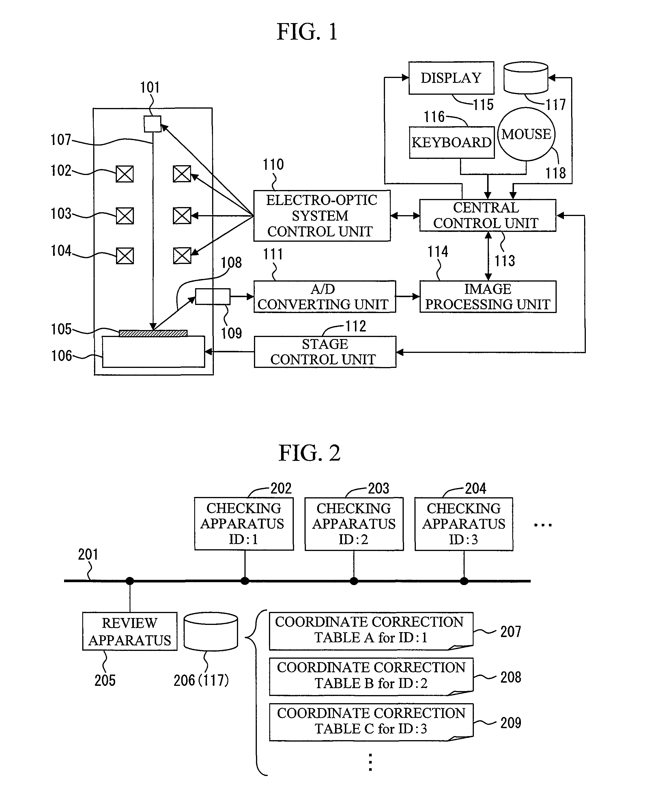
The present invention provides a method and apparatus for correcting coordinates to properly and quickly arrange a sample in a field of view for review. The review apparatus identifies a combination of a checking apparatus and a calculation condition to calculate coordinates, and selects one of multiple coordinate correction tables based on the combination to correct the coordinates. The accuracy of the correction is evaluated, and an optimal correction table can be automatically selected for use. This improves defect detection performance by increasing a low magnification, particularly in the ADR.

Problems solved by technology

However, a too high magnification may cause the defect to be out of the view field if a deviation of the position is substantial.
Because of this, ADR configuration has a difficulty in setting a parameter of a magnification for a low magnification image, so that user experience is needed for the setting.
However, if there are a plurality of higher-level checking apparatuses, or if different deviation tendencies are shown depending on, for example, check conditions or a deviation tendency changes over time even in the case of that there is only a single checking apparatus, the optimal correction result cannot be obtained using a single correction table.

Method used


Image

  • Method of correcting coordinates, and defect review apparatus
  • Method of correcting coordinates, and defect review apparatus
  • Method of correcting coordinates, and defect review apparatus

Examples


first embodiment

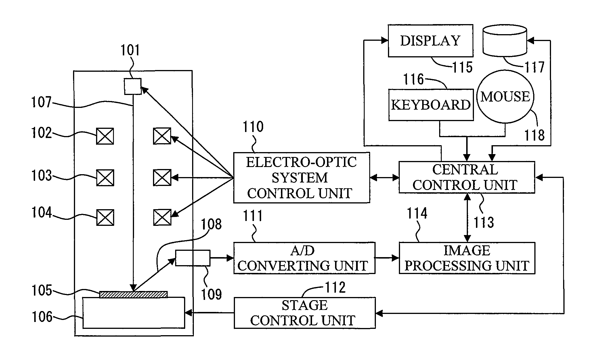
[0024]FIG. 1 is a cross-sectional view of configuration of an SEM-based semiconductor defect review apparatus (a review apparatus) according to an embodiment of the present invention. The SEM-based defect review apparatus in FIG. 1 consists of an electron gun 101, a lens 102, a deflector 103, an objective lens 104, a sample 105, a stage 106, a secondary particle detector 109, an electro-optic system control unit 110, an A / D converting unit 111, a stage control unit 112, a central control unit 113, an image processing unit 114, a display 115, a keyboard 116, a storage device 117, a mouse 118 and the like.

[0025]An electron beam 107 emitted by the electron gun 101 converges on the lens 102, is deflected on the deflector 103, converges on the objective lens 104 and then is radiated onto the sample 105. Secondary particles 108 such as secondary electrons or reflected electrons are generated from the sample 105 radiated with the electron beam 107 depending on a form or materials of the sa...

second embodiment

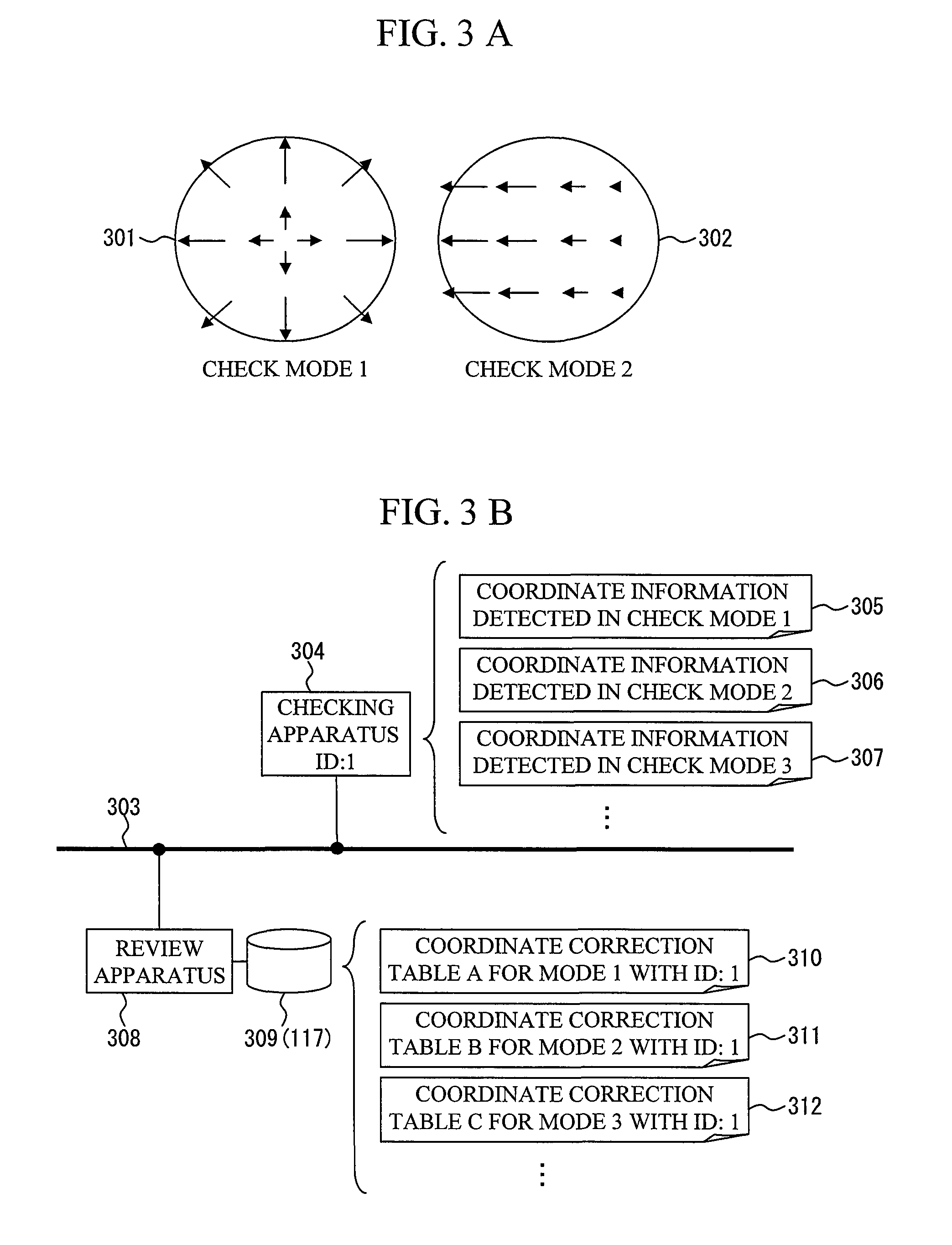
[0032]As described above, the review apparatus according to the first embodiment selects a coordinate correction table statically in correspondence to a check mode of the checking apparatus. That is, a checking apparatus and a check mode uniquely decide a coordinate correction table.

[0033]However, because of temporal changes or the like in the apparatus, a coordinate correction table decided uniquely depending on a check mode is not always an optimal table. Although periodical maintenance is effective to the temporal changes as described above, its steps must be extremely complicated.

[0034]To address the above problem, according to a second embodiment, even if a checking apparatus and / or a review apparatus change with a certain tendency over time, a plurality of coordinate correction tables are prepared in correspondence to the temporal changes, or a plurality of coordinate correction tables are prepared in correspondence only to a plurality of check modes to always switch dynamical...


PUM


Abstract

The present invention provides a method of correcting coordinates so as to quickly and properly arrange a sample in a field of view in a review apparatus for moving a sample stage onto the specified coordinates to review the sample. A review apparatus according to the present invention, which is a review apparatus for moving a sample stage onto coordinates previously calculated by a checking apparatus to review the sample, has a function of retaining a plurality of coordinate correction tables to correct a deviation between a coordinate value previously calculated by a checking apparatus and an actual sample position detected by the review apparatus. The review apparatus evaluates correction accuracy of the plurality of coordinate correction tables and applies one of the coordinate correction tables with the maximum evaluation value.

Description

BACKGROUND OF THE INVENTION[0001]1. Field of the Invention[0002]The present invention relates to a method and apparatus for correcting coordinates so as to arrange a sample in a field of view in a review apparatus for moving a sample stage onto the specified coordinates to review the sample. More particularly, the present invention relates to an apparatus for deciding a position for review based on information of a position of a defect detected by a higher-level checking apparatus like an SEM (Scanning Electron Microscope) based defect review apparatus.[0003]2. Background Art[0004]In semiconductor manufacturing, it is important to find defects appearing during a manufacturing process in early phases and take measures against the defects in order to ensure yield enhancement. In recent years, even slight defects have nonnegligible effects on yields as semiconductors become smaller, hence making the size of defects to be reviewed smaller.[0005]An SEM-based defect review apparatus is an...

Claims


Application Information

Patent Timeline
Patent Type & Authority Patents(United States)
IPC IPC(8): G01C17/38G21C17/00H01J37/20H01J37/28H01L21/66
CPCG01R31/2884
Inventor HIRAI, TAKEHIROAOKI, KAZUOKANEKO, KUMI
Owner HITACHI HIGH-TECH CORP
Learn More