Angiographic injector and injection method

a technology of injector and angiography, which is applied in the field of angiography, can solve the problems of no safety limits, the quantity of radiographic contrast material is typically limited to a maximum of about 12 cc, and the most manual systems can only inject the maximum amount of radiographic contrast material at the maximum

Inactive Publication Date: 2010-07-13
INVASATEC
View PDF92 Cites 33 Cited by
  • Summary
  • Abstract
  • Description
  • Claims
  • Application Information

AI Technical Summary

Benefits of technology

[0015]The present invention is an angiographic injection system which includes both high pressure and low pressure systems. The high pressure system includes a motor driven injector pump which supplies radiographic contrast material under high pressure to a catheter. The low pressure system includes, for example, a pressure transducer for measuring blood pressure and a pump which is used to both for delivering saline solution to the patient and for aspirating waste fluid. In the present invention, a manifold is connected to the syringe pump, the low pressure system, the catheter which is inserted into the patient. A valve associated with the manifold is normally maintained in a first state which connects the low pressure system to the catheter through the manifold. When pressure from the syringe pump reaches a predetermined level, the valve switches to a second state which connects the syringe pump to the catheter, while disconnecting the low pressure system from the catheter.

Problems solved by technology

However, generally, most manual systems can only inject the radiographic contrast material at maximum pressure that can be applied by the human hand (i.e., 150 p.s.i.).
Also, the quantity of radiographic contrast material is typically limited to a maximum of about 12 cc.
Moreover, there are no safety limits on these manual contrast injection systems which restrict or stop injections that are outside of predetermined parameters (such as rate or pressure) and there are no active sensors to detect air bubbles or other hazards.
The lack of ability to vary the rate of injection during injection can result in suboptimal quality of angiographic studies.
Consequently, the initial injection of contrast material may be insufficient in volume or flow rate to outline a desired structure on an x-ray image, necessitating another injection.
Conversely, an excessive flow rate might injure the chamber or blood vessel being injected, cause the catheter to be displaced (from the jet of contrast material exiting the catheter tip), or lead to toxic effects from contrast overdose (such as abnormal heart rhythm).

Method used


Image

  • Angiographic injector and injection method
  • Angiographic injector and injection method
  • Angiographic injector and injection method

Examples


Embodiment Construction

A. application Ser. No. 08 / 426,149

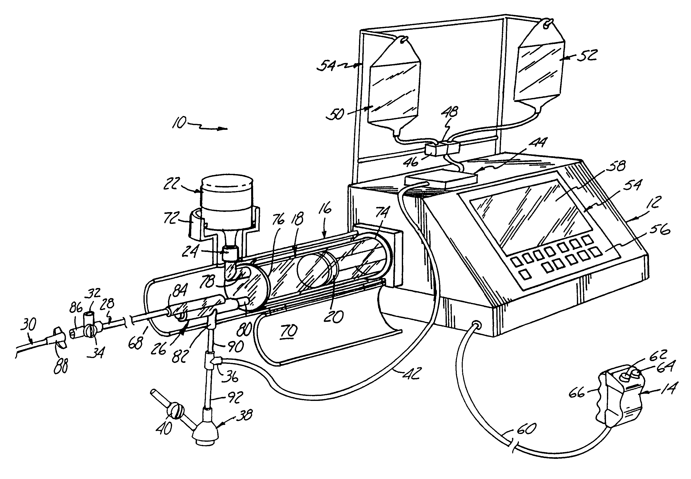
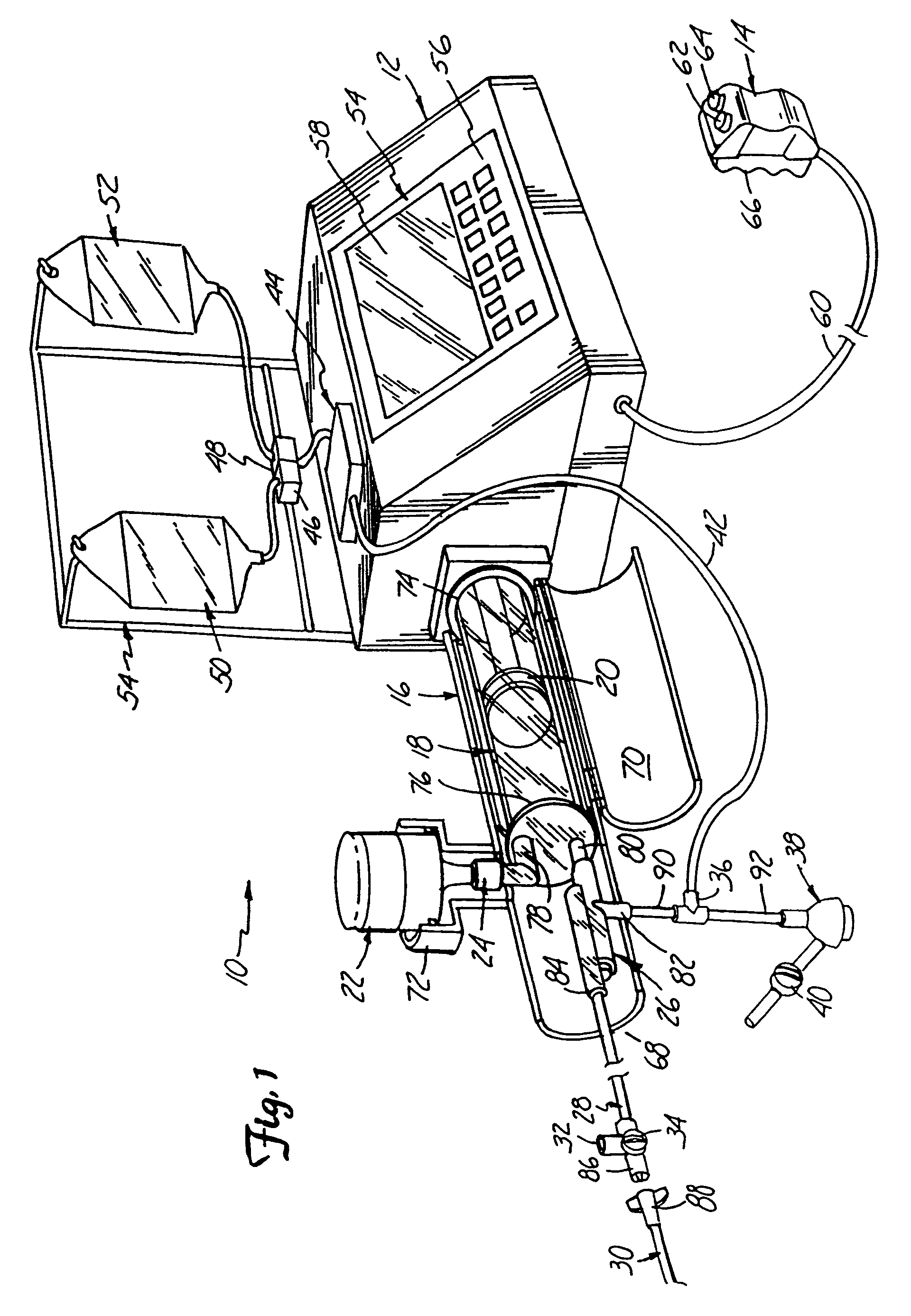
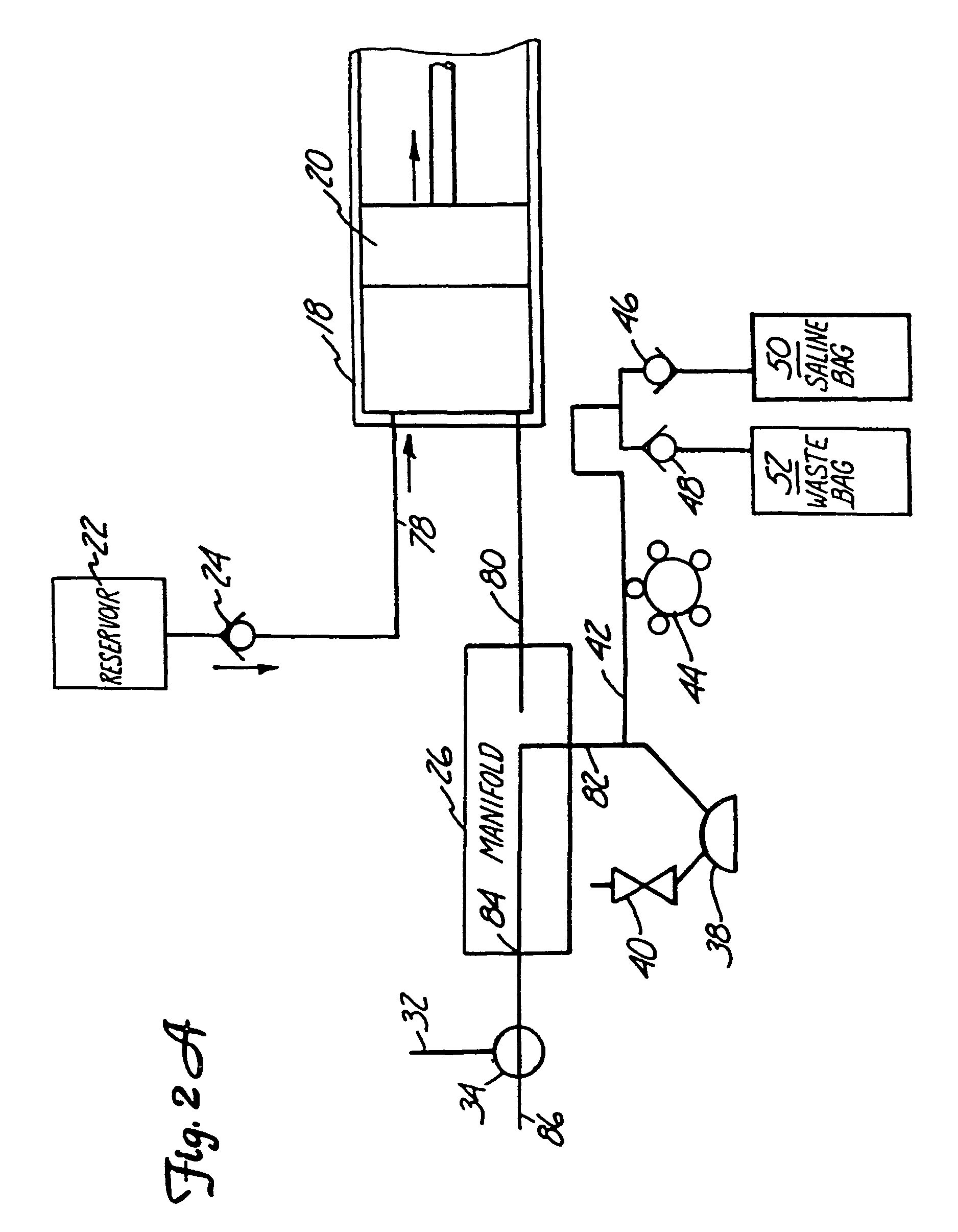
[0045]FIG. 1 shows angiographic injector system 10 for injecting radiographic contrast material into a blood vessel under interactive physician control. System 10 includes main console 12, hand held remote control 14, syringe holder 16, syringe body 18, syringe plunger 20, radiographic material reservoir (bottle) 22, one-way valve 24, manifold 26, high pressure tube 28, catheter 30, patient medication port 32, three-way stop-cock 34, T-connector 36, pressure transducer 38, stop-cock 40, tubing 42, peristaltic pump 44, saline check valve 46, waste check valve 48, saline bag 50, waste bag 52, and bag support rack 54.

[0046]Console 12 houses the electrical controls for system 10, together with the motors which drive piston 20 and peristaltic pump 44. On the front surface of console 12, user interface 54 provides control switches 56 and display 58 through which the user may enter control settings and monitor the operational state of system 10.

[0047]Remot...


PUM


Abstract

An angiographic injector system includes a manifold and valve which selectively connects either a syringe pump or a low pressure system to a catheter which is inserted into a patient. The valve is normally biased to a state which connects the low pressure system to the catheter for pressure monitoring, saline flushing, or aspirating functions. When an injection is to be made, the valve automatically switches so that the low pressure system is disconnected and not exposed to high pressure, while the syringe pump is connected through the manifold to the catheter.

Description

RELATED APPLICATIONS[0001]This application is a continuation of U.S. Ser. No. 09 / 591,529, filed Jun. 9, 2000, now U.S. Pat. No. 6,656,157 which is a continuation of U.S. Ser. No. 08 / 957,801, filed Oct. 24, 1997, now U.S. Pat. No. 6,221,045, which is continuation-in-part of U.S. Ser. No. 08 / 946,293, filed Oct. 7, 1997, now U.S. Pat. No. 5,800,397, which is a file wrapper continuation application of U.S. Ser. No. 08 / 426,148, filed Apr. 20, 1995, now abandoned, which applications are hereby incorporated by reference.FIELD OF THE INVENTION[0002]This invention relates to angiography and more specifically, the injector system used to inject a medical fluid such as radiographic contrast material into living organisms.BACKGROUND OF THE INVENTION[0003]One of the major systems in the human body is the circulatory system. Components of the circulatory system include the heart, blood vessels, and blood, all of which are vital for the transportation of materials between the external environment ...

Claims


Application Information

Patent Timeline
Patent Type & Authority Patents(United States)
IPC IPC(8): A61M1/00A61M31/00A61M37/00A61B6/00A61M5/00A61M5/145A61M5/168
CPCA61B6/481A61M5/007A61M5/14216A61M5/14546A61M5/16827A61B6/504A61B6/548A61M5/001A61M5/14232A61M5/1723A61M5/36A61M5/365A61M2005/1403A61M2205/3313A61M2205/3561A61M2209/01A61M2230/04Y10S128/01
Inventor DUCHON, DOUGPAULSON, THOMASWILSON, ROBERT F.LIU, JIYAN
Owner INVASATEC
Why Eureka
Try Eureka