Miniaturized high conductivity thermal/electrical switch

a high-conductivity, switch technology, applied in the direction of thermal micromechanical switches, thermal switch details, applications, etc., to achieve the effect of improving on/off modulation, high thermal and electrical conductivity

Inactive Publication Date: 2010-07-13
AAC CLYDE SPACE AB
View PDF15 Cites 36 Cited by
  • Summary
  • Abstract
  • Description
  • Claims
  • Application Information

AI Technical Summary

Benefits of technology

[0011]The high conductivity switch according to the invention comprises a sealed cavity with a first wall and a second wall, wherein at least the second wall is a membrane assembly. The second wall is adapted to be arranged with a gap to a receiving structure. A thermal actuator material that is adapted to change volume with temperature fills a portion of the cavity. A conductor material fills another portion of the cavity. The conductor material provides a high conductivity transfer structure between the first wall and the second wall. The thermal actuator material is arranged to upon a temperature induced volume change, displace the second wall, so that the gap to the receiving structure can be bridged, providing a high conductivity contact from the first wall to the receiving structure.
[0016]Thanks to the invention it is possible to provide miniaturized mechanical switches with improved on / off modulation with respect to high thermal and electrical conductivity.
[0017]One advantage of the switch according to the invention is that the switch can be arranged to be automatically and reversibly activated by the heat generated by the heat source.

Problems solved by technology

Obviously the prior art has drawbacks with regards to being able to provide thermally controlled high conductivity switches with high switching capability compared to the physical size of the switch.

Method used


Image

  • Miniaturized high conductivity thermal/electrical switch
  • Miniaturized high conductivity thermal/electrical switch
  • Miniaturized high conductivity thermal/electrical switch

Examples


Embodiment Construction

[0030]A high conductivity switch according to the present invention opens new possibilities for thermal and electrical control and for the implementation of different miniaturized systems, particularly in space applications.

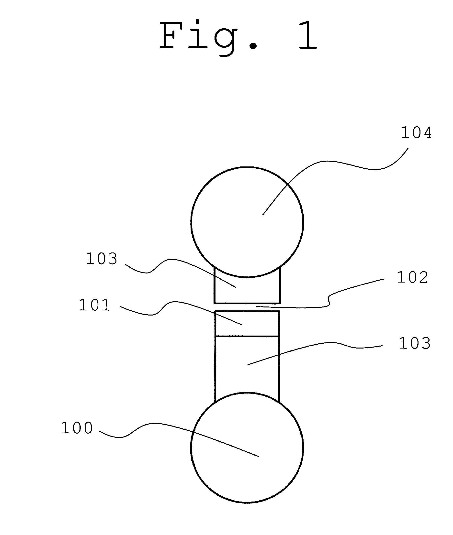
[0031]An active thermal control system is schematically illustrated in FIG. 1. If an excessive amount of heat is generated in an arbitrary device 100, i.e. the heat source, it might be necessary to conduct some heat away from the device 100 in order to avoid overheating. This is accomplished through one or two heat conductors 103 to a thermal heat sink 104, which can be a radiator or a latent heat storage device. The two heat conductors 103 are separated by an air gap 102 in sequence with a thermal switch 101. At a certain predetermined temperature the switch 101 closes the air gap 102 permitting a high heat flux to flow from the heat source 100 to the heat sink 104. A desired feature of the thermal switch 101 is to have as high temperature modulation as possible...


PUM


Abstract

The present invention is a thermally controlled switch with high thermal or electrical conductivity. Microsystems Technology manufacturing methods are fundamental for the switch that comprises a sealed cavity formed within a stack of bonded wafers, wherein the upper wafer comprises a membrane assembly adapted to be arranged with a gap to a receiving structure. A thermal actuator material, which preferably is a phase change material, e.g. paraffin, adapted to change volume with temperature, fills a portion of the cavity. A conductor material, providing a high conductivity transfer structure between the lower wafer and the rigid part of the membrane assembly, fills another portion of the cavity. Upon a temperature change, the membrane assembly is displaced and bridges the gap, providing a high conductivity contact from the lower wafer to the receiving structure.

Description

[0001]This application is a U.S. National Phase Application under 35 USC 371 of International Application PCT / SE2007 / 050030 filed Jan. 18, 2007, which claims the benefit of Swedish Patent Application No. 0600096-2 filed Jan. 18, 2006.TECHNICAL FIELD OF THE INVENTION[0002]The present invention relates to a structure for thermal or electrical control, particularly for thermal control in space applications.BACKGROUND OF THE INVENTION[0003]In many devices, wherein a substantial amount of heat is generated, there is a need for an active thermal control, in order to maintain the desired operational temperature for the device. A common solution is to use the air in the atmosphere for transport of the excessive heat by use of electromechanical fans or ventilators. This is an effective but sometimes noisy solution, wherefore conduction of the heat through passive or active heat conductors to a thermal radiator in many times is a preferred solution. In particular, in space applications, opera...

Claims


Application Information

Patent Timeline
Patent Type & Authority Patents(United States)
IPC IPC(8): H01H37/48F28F27/00F25D29/00
CPCH01H37/36H01H37/46H01H2037/008
Inventor STENMARK, LARS
Owner AAC CLYDE SPACE AB
Why Eureka
Try Eureka